
Audio Codec '97

AC ‘97 Component Specification Revision 2.3 Rev 1.0
60
should result in the “Validity” flag being set to “1”. In the case where the S/PDIF transmitter does is not
receiving a sample or does not receive a valid sample from the AC’97 controller, (Left or Right), the
S/PDIF transmitter should set the S/PDIF "Validity” flag to “0” and pad each of the S/PDIF “Audio Sample
Word” in question with "0"s for the sub-frame in question. If a valid sample (Left or Right) was received
and successfully transmitted, the "Validity” flag should be "0" for that sub-frame.
• If “V”=1 and “VCFG” = 0, then each S/PDIF subframe (Left & Right) should have bit<28> “Validity”
flag = 1. This tags all S/PDIF sub-frames as invalid.
• “V”=1 and “VCFG”=1 state is reserved for future use.
• Default state, coming out of reset, for “V” and “VCFG” should be 0 and 0 respectively.
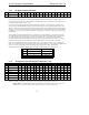
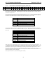
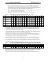
5.8.3 Audio Sample Rate Control Registers (Index 2Ch – 34h)
Reg Name D15 D14 D13 D12 D11 D10 D9 D8 D7 D6 D5 D4 D3 D2 D1 D0 Default
2Ch PCM Front DAC Rate
(output slots 3, 4, 6)
SR15 SR14 SR13 SR12 SR11 SR10 SR9 SR8 SR7 SR6 SR5 SR4 SR3 SR2 SR1 SR0 BB80h
2Eh PCM Surr DAC Rate
(output slots 7, 8)
SR15 SR14 SR13 SR12 SR11 SR10 SR9 SR8 SR7 SR6 SR5 SR4 SR3 SR2 SR1 SR0 BB80h
30h PCM LFE DAC Rate
(output slot 9)
SR15 SR14 SR13 SR12 SR11 SR10 SR9 SR8 SR7 SR6 SR5 SR4 SR3 SR2 SR1 SR0 BB80h
32h PCM L/R ADC Rate
(input slots 3, 4)
SR15 SR14 SR13 SR12 SR11 SR10 SR9 SR8 SR7 SR6 SR5 SR4 SR3 SR2 SR1 SR0 BB80h
34h Mic ADC Rate
(input slot 6)
SR15 SR14 SR13 SR12 SR11 SR10 SR9 SR8 SR7 SR6 SR5 SR4 SR3 SR2 SR1 SR0 BB80h
In Variable Rate Audio (VRA) or Mic (VRM) modes, DACs and ADCs are governed by read/write sample rate
control registers that contain 16-bit unsigned values between 0 and 65535, representing the rate of operation in Hz.
DAC and ADC groups should be capable of operating at independent rates, otherwise a currently active DAC or
ADC rate may limit availability of the associated converter.
In both VRA and VRM modes, if the value written to the register is supported that value will be echoed back when
read, otherwise the closest (higher in case of a tie) sample rate supported is returned.
In Double Rate Audio (DRA) mode, the programmed audio DAC sample rates programmed are multiplied by 2x.
As an example: For 88.2 kHz DAC operation, the sample rate programmed would be 44.1 kHz, and the DRA bit
will be programmed to 1. DRA does NOT affect input ADC operation.
Variable Rate Audio is essential to low cost integrated audio solutions
the minimum requirement is dual-rate
operation at either 44.1 or 48 kHz, with additional support for 8.0, 11.025, 16, 22.05, and 32 kHz recommended.
The default value after cold or register reset for the audio sample rate control registers is BB80h (48 kHz) and
VRA=0. When VRA is set to 0 the registers are forced to BB80h (48 kHz) because that is the only rate supported,
and any values previously written to these registers are lost.
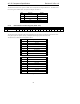
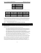
5.8.4 Surround and Center/LFE Volume Control Registers (Index 36h and 38h)
Reg Name D15 D14 D13 D12 D11 D10 D9 D8 D7 D6 D5 D4 D3 D2 D1 D0 Default
36h Center/LFE Volume Mute x LFE5 LFE4 LFE3 LFE2 LFE1 LFE0 Mute x CNT5 CNT4 CNT3 CNT2 CNT1 CNT0 8080h
38h Surround Volume Mute x LSR5 LSR4 LSR3 LSR2 LSR1 LSR0 Mute x RSR5 RSR4 RSR3 RSR2 RSR1 RSR0 8080h
These read/write registers control the output volume of the optional four PCM channels, and applies to monolithic
multichannel Codecs. Values written to the fields behave the same as the Play Master Volume Register (Index 02h),
which offers attenuation but no gain. There is an independent mute (1=on) for each channel.
The default value after cold or register reset for this register (8080h) corresponds to 0 dB attenuation with mute on.