
Audio Codec '97

AC ‘97 Component Specification Revision 2.3 Rev 1.0
69
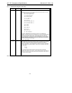
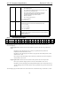
07h – SPDIF In (electrical)
08h – SPDIF In (TOS)
09h – Headset (mono speaker left channel and microphone. Read
Functions 0 to 3 for matching DAC out)
0Ah – Other. Allows a vendor to report sensing other type of
devices/peripherals. SR[5:0] together with OR[1:0] provide
information regarding the type of device sensed.
0Bh-0Eh – Reserved
0Fh – Unknown (use fingerprint)
10-1Fh – Reserved
This field is Read Only.
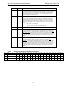
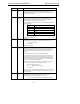
OR[1:0] 0h Order Bits
These bits indicate the order the sensed result bits SR[5:0] are using.
00 – 10
0
(i.e., Ohms)
01 – 10
1
(i.e., 10 Ohms)
10 – 10
2
(i.e., 100 Ohms)
11 – 10
3
(i.e., 1K Ohms)
SR[5:0] 0h Sense Result bits
These bits are used to report a vendor specific fingerprint or value. (Resistance,
impedance, reactance, etc)
This field is Read Only.
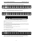
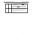
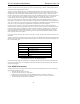
5.9.3 Slot Mapping Descriptor
Reg Name D15 D14 D13 D12 D11 D10 D9 D8 D7 D6 D5 D4 D3 D2 D1 D0 Default
6Ch DAC Slot Mapping FD3 FD2 FD1 FD0 SD3 SD2 SD1 SD0 CLD3 CLD2 CLD1 CLD0 X X X X 3760h
6Eh ADC Slot Mapping LIA3 LIA2 LIA1 LIA0 IMA3 IMA2 IMA1 IMA0 X X X X X X X MV 3600h
The Slot Mapping Descriptor page provides a way for the controlling software to modify the default slot to
DAC/ADC mappings.
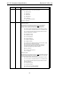
Page 01 register 6Ch controls the slots from which the DACs present in the codec will get the data to
render.
Bits FD[3:0] control the mapping of the 1st DAC pair (generally the front speakers and
headphone), which defaults to slots 3 and 4.
Bits SD[3:0] control the mapping of the 2nd DAC pair (generally the surround speakers), which
defaults to slots 7 and 8.
Bits CLD[3:0] control the mapping of the 3rd DAC pair (generally the center and LFE speakers),
which defaults to slots 6 and 9.
Page 01 register 6Eh controls the slots onto which the ADCs present in the codec will place data.
Bits LIA[3:0] control the mapping of the Line In ADC, which defaults to slots 3 and 4.
Bits IMA[3:0] control the mapping of the Independent Microphone ADC, which defaults to slot 6.
The MV (Mapping Valid) bit indicates that the values programmed into page offsets 6Ch and 6Eh
are valid.
The Slot Mapping registers must default to the values defined as the slot default for the given DAC/ADC, as above.