
Audio Codec '97


AC ‘97 Component Specification Revision 2.3 Rev 1.0
73
thereby preserving 100% of the digital content. If supported, SPCV should indicate valid configuration when
programmed as follows:
• Register 2Ch controlling AC-link slots 3&4 DAC sample rates set to “xxxxh” (32, 44.1 or 48kHz)
• Register 3Ah, field SPSR[1,0] controlling S/PDIF sample rate set to “xxh” (32, 44.1, or 48kHz)
• slot 3&4 DAC sample rate matches selected SPSR
• Register 2Ah, field SPSA[1,0] controlling S/PDIF slot assignment set to “00” (slots 3&4)
This option expands “bit exact” S/PDIF transmission to all common S/PDIF rates, not just 48 kHz.
6. Modem AFE Features
6.1 Overview
The purpose of this extension is to define optional interoperable methods for implementing modem analog front-end
(AFE) functionality and accessing it via AC-link. This includes:
• Slot assignments for line, handset, and GPIO pin status and control
• GPIO pin status and control definitions
• Modem AFE register definitions
• Power management and wake-up event definitions
• CallerID string transmission via AC-link definitions
• Loopback testing definitions
6.2 Slot Assignments for Modem
SYNC
Slot #
0 1 2 3 4 5 6 7 8 9 10 11 12
SDATA_OUT
SDATA_IN
CMD
ADDR
CMD
DATA
PCM
L FRONT
PCM PCM
CENTER
PCM
L SURR
PCM
R SURR
PCM
LFE
LINE 2
DAC
HSET
DAC
TAG
STATUS
ADDR
STATUS
DATA
PCM
LEFT
PCM
RIGHT
IO
STATUS
RSRVD RSRVD
LINE 2
A
DC
HSET
A
DC
TAG
IO
CTRL
LINE 1
A
DC
SLOTREQ 3-12
RSRVD
LINE 1
DAC
PCM
MIC
Codec ID
R FRONT
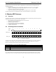
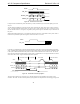
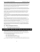
Figure 19. AC-link Slot Assignments
As shown in Figure 19, the line1, line2, and handset streams have been assigned to slots 5, 10, and 11 respectively.
As with AC ‘97 , the leading 16-bits of each slot must contain valid sample data; support for 18 or 20-bits is
optional. The following table describes the input and output slot data format.
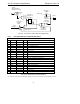
Input and Output Slots 5, 10, 11: Line1, Line2, Handset ADCs and DACs
Bit Description
19-4 16-bit sample (MSB bit 19, LSB bit 4)
3-0 Optional: LSBs of 18 or 20-bit sample
Table 39. Slots 5, 10, and 11-Bit Definitions
Up to 16-bits of GPIO status (input) and control (output) have been directly assigned to bits on slot 12 in order to
minimize latency of access. This allows software to monitor changing conditions without the latency imposed by