
Audio Codec '97

AC ‘97 Component Specification Revision 2.3 Rev 1.0
75
Config (4Ch.
n
)
(0=output)
Polarity (4Eh.
n
)
•0=CMOS
•1=Open Drain
GPIO.
n
Output
GPIO.
n
Polarity (4Eh.
n
)
•0=Low active
•1=High active
S
R
Q
Q
Config (4Ch.
n
)
Sticky (50h.
n
)
Interrupt
•SDATA_IN (wake up)
•GPIO_INT (slot 12, bit 0)
Other 15
bits...
1
0
Sticky (50h.
n
)
Write ‘0’ to
GPIO Status (54h.
n
)
Wake (52h.
n
)
GPIO
Status (54h.
n
)
input buffer
(non -inverting)
1
0
Config (4Ch.
n
)
•0=Output
•1=Input
.
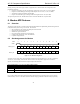
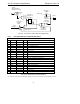
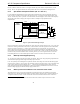
Figure 20. “Conceptual” Example of GPIO Pin Implementation
6.3.2 Recommended Slot 12 GPIO Bit Definitions
Slot 12 (Input and Output): GPIO bits
Bit GPIO Name Sense Description
19 GPIO15 LINE2_HL2R out opt GPIO / HANDSET_TO_LINE2 relay control (out)
18 GPIO14 LINE2_PULSE In/out opt GPIO / Line 2 pulse dial (out)
17 GPIO13 LINE2_LCS in Loop Current Sense Line 2
16 GPIO12 LINE2_CID out Caller ID path enable Line 2
15 GPIO11 LINE2_RI in Ring Detect Line 2
14 GPIO10 LINE2_OH out Off Hook Line 2
13 GPIO9 LINE12_RS in/out opt GPIO / International Bit 3 / Line 1/2 RS (out)
12 GPIO8 LINE12_DC in/out opt GPIO / International Bit 2 / Line 1/2 DC (out)
11 GPIO7 LINE12_AC in/out opt GPIO / International Bit 1 / Line 1/2 AC (out)
10 GPIO6 LINE1_HOHD in/out opt GPIO / HANDSET off hook detect (in)
9 GPIO5 LINE1_HL1R in/out opt GPIO / HANDSET to Line 1 relay control (out)
8 GPIO4 LINE1_PULSE in/out opt GPIO / Line 1 pulse dial (out)
7 GPIO3 LINE1_LCS in Loop Current Sense Line 1
6 GPIO2 LINE1_CID out Caller ID path enable Line 1
5 GPIO1 LINE1_RI in Ring Detect Line 1
4 GPIO0 LINE1_OH out Off Hook Line 1
1-3 Vendor specific vendor optional
0 GPIO_INT GPIO_INT (uses same logic as wake-up event)
Table 41. Recommended Slot 12 GPIO Bit Definitions
AC ‘97 makes no requirement on the number of GPIOs or their use, only that they be implemented as general