
Audio Codec '97

AC ‘97 Component Specification Revision 2.3 Rev 1.0
78
SDATA
_
OUT
TAG
SYNC
BIT_CLK
Write to
0x26
Data
PR4
slot 12
prev. frame
TAG
slot 12
prev. frame
SDATA
_
IN
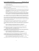
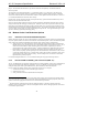
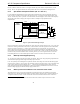
Figure 22. AC-link Low Power Mode
In response to this command BIT_CLK and SDATA_IN Codec, and SDATA_OUT controller outputs go low and
stay low.
AC-link when programmed to its low power mode, can be reactivated only by the device driver, which can write to
an AC ‘97 Digital Controller register causing it to signal a cold or warm reset on the AC-link. A warm reset, which
will not alter the current AC ‘97 registers, is signaled by driving SYNC high for a minimum of 1
µs in the absence of
BIT_CLK.
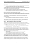
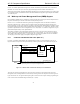
Within normal audio frames SYNC is a synchronous Codec input. However, in the absence of BIT_CLK, SYNC is
treated as an asynchronous input used to signal a warm reset to the AC ‘97 Codec.
SYNC
BIT_CLK
Figure 23. AC-link Warm Reset
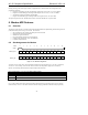
In an AMC ‘97 implementation, where the audio/modem AFE Codec and AC-link are both completely powered by
Vaux, an enabled power management event detected at the modem interface causes the assertion of the PME# signal
to the system. PME# assertion causes the system to resume so that the modem event can be serviced. The device
driver must first reestablish communications with the Codec to command the AC ‘97 Digital Controller to execute a
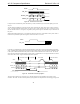
warm reset to the AC-link. Figure 24 illustrates the entire sequence:
SDATA_OUT
TAG
SYNC
BIT_CLK
Write to
0x26
Data
PR4
slot 12
p
rev. frame
TAG
slot 12
p
rev. frame
SDATA_IN
PME#
(
Audio controller wake re
q
uest to s
y
stem
)
TAG Slot 1 Slot 2
Power Down Frame
Wake Event
Sleep State
New Audio Frame
TAG Slot 1 Slot 2
Figure 24. AC-link Power-down/Up Sequence
The rising edge of SDATA_IN causes the AC ‘97 Digital Controller to assert its PME# to the system’s ACPI
controller. The AMC ‘97 Codec must keep SDATA_IN high until it has sampled SYNC first having gone high, and