
Audio Codec '97

AC ‘97 Component Specification Revision 2.3 Rev 1.0
80
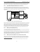
initialize. In the case of the combined Codec (AMC ‘97 ), the entire Codec, AC-link, and portions of the AC ‘97
Digital Controller are powered by Vaux which enables Caller ID decode and store to be done either by the controller
or by the modem AFE Codec. However in the case of the split partitioned design, only the MC ‘97 SDATA_IN
signal on the AC-link is powered while the remainder of the AC-link is un-powered. In this case the Caller ID
decode and store operations must be supported in the MC ‘97 Codec.
If the maximum delay from a PME# event to power pins on the PCI Bus at 95% full value is under 2 seconds,
controller manufacturers may be able to load the Caller ID code and wait for the incoming data before the driver has
an opportunity to configure the part and assign it resources. The controller then may present the Caller ID data to
the driver when it is loaded.
The resume time for a PC in D3 cold also precludes host-based processing of the caller ID burst, in both the U.S.
and Europe. (A)MC ‘97 Codecs which serve as the AFE for host-based modem implementations may find it
attractive to support Caller ID decode functionality in addition to simple wake-up on ring detect. Such a Codec
would be able to automatically decode and save the caller ID string until the PC system and AC ‘97 Digital
Controller have resumed.
The optional CID1 and CID2 bits in the Miscellaneous Modem AFE Status and Control Register have been defined
to indicate to the awakened AC ‘97 Digital Controller that decoded caller ID string data is available for Line1
(CID1=1) or Line2 (CID2=1). ADC input slots 5 (for Line 1) and 10 (for Line 2) can be used to transfer the caller
ID string data, two bytes per AC-link input frame until completed, at which time the CIDn bit automatically resets
(goes inactive).
The AC ‘97 Digital Controller initiates the stored caller ID string transfer by strobing (writing) CIDn=1 and
subsequently reading data from input slot 5 (for Line 1) or 10 (for Line 2) until the tag bit and (and as a
consequence, CIDn) becomes inactive. To prevent unnecessary register access to Register 3Ch, the tag bit should
go inactive for at least one AC-link frame between Caller ID string transfer and ADC transfer. A strobe (write) of
CIDn=0 will clear or cancel the caller ID transmission and reset the CIDn indicator. Once the CIDn bit is reset
(automatically or manually), the slot resumes transfer of ADC input data.
Data from the caller ID string can be handled two ways. It can either be demodulated only (raw) or demodulated
and preprocessed to delete the channel seizure time and mark signal time, etc. It requires slightly more RAM
(approx. 50 bytes) to retain a raw string, but less decoder intelligence. The CIDR bit in the Miscellaneous Modem
AFE Status and Control Register indicates which method the Codec caller ID supports. CIDR=1 indicates that
stored caller ID data is raw.
6.6 Modem AFE Register Definitions
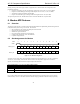
6.6.1 Extended Modem ID Register (Index 3Ch)
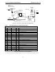
Reg Name D15 D14 D13 D12 D11 D10 D9 D8 D7 D6 D5 D4 D3 D2 D1 D0 Default
3Ch Extended Modem ID ID1 ID0 x x x x x x x x x CID2 CID1 HSET LIN2 LIN1 xxxxh
The extended modem ID is a read/write register that primarily identifies the enhanced Codec’s modem AFE
capabilities. The default value will depend on features and hardware configuration. Writing any value to this
register performs a warm modem AFE reset (register range 3C-56h), including GPIO (register range 4C-54h). The
warm reset causes all affected registers to revert to their default values. Note: for AMC ‘97 parts the audio and
modem AFE should be logically independent (writes to Register 00h resets audio only).
• LIN1=1 indicates 1st line is supported
• LIN2=1 indicates 2nd line is supported
• HSET=1 indicates handset DAC/ADC is supported
• CID1=1 indicates that caller ID decode for line 1 is supported
• CID2=1 indicates that caller ID decode for line 2 is supported
• ID1, ID0 is a 2-bit field which indicates the Codec configuration: Primary is 00; Secondary is 01, 10, or 11
If LIN1=1, then the Codec is an (A)MC ‘97 , and all modem functionality should be implemented and controlled via