
Audio Codec '97

AC ‘97 Component Specification Revision 2.3 Rev 1.0
81
the newly-defined Extended AC ‘97 registers. In particular, it is required that the following functionality NOT be
implemented as defined in the original AC 97 Component Specification:
• Reset Register (Index 00h) bit 1: Modem line Codec support (ID1)
• Reset Register (Index 00h) bit 6-9 audio DAC and ADC resolution do not have any MAFE resolution
information
• General Purpose Register (Index 20h) bits 10, 11: Local Loopback (LLBK) and Remote Loopback (RLBK)
• Modem Rate (Index 24h) Register
• Power-down/Ctrl/Stat (Index 26h) bits 4 ,15: Modem Ready (MDM) and Modem DAC/ADC off (PR7)
Modem DAC and ADC resolution is by default 16-bits. Modem interoperability is not expected between AC `97
Controller/Codec pairs that aren't designed to work together, but vendor specific methods can be used to identify and
support 18- or 20-bit resolution. For example, an AC `97 Controller could determine the modem DAC/ADC
resolution in an MC or AMC Codec by inspecting the Vendor ID Registers.
The value after cold or register reset for this register is constant, and depends on features supported and hardware
configuration as Primary or Secondary Codec.
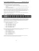
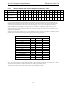
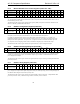
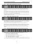
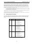
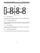
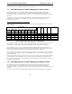
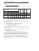
6.6.2 Extended Modem Status and Control Register (Index 3Eh)
Reg Name D15 D14 D13 D12 D11 D10 D9 D8 D7
D6
D5
D4
D3 D2 D1 D0 Default
3Eh Ext’d Modem Stat/Ctrl PRH PRG PRF PRE PRD PRC PRB PRA HDAC HADC DAC2 ADC2 DAC1 ADC1 MREF GPIO FFxxh
The Extended Modem Status and Control Register functions similarly to the original AC ‘97 Power-down
Control/Status Register, located at index 26h. The (A)MC ‘97 Codec must restrict modem and handset power-down
control/status to this register since all of the functions are provided here. Therefore, the (A)MC ‘97 Codec (and AC
‘97 Digital Controller, of course) must not implement MDM and PR7 in Register 26h and use what is included here.
When the GPIO section is powered down, all outputs must be tri-stated and input slot 12 should be marked invalid
when the AC-link is active. When slot 12 is invalid, Register 54h (GPIO Pin Status Register) will report 0s. In
addition the Codec should force SDATA_IN slot 12 to all 0s.
Bits 7-0 are read only, 1 indicates modem AFE subsystem readiness:
• GPIO=1 indicates GPIO ready
• MREF=1 indicates Modem Vref’s up to nominal level
• ADC1=1 indicates Modem Line 1 ADC ready
• DAC1=1 indicates Modem Line 1 DAC ready
• ADC2=1 indicates Modem Line 2 ADC ready
• DAC2=1 indicates Modem Line 2 DAC ready
• HADC=1 indicates Handset ADC ready
• HDAC=1 indicates Handset DAC ready
Bits 15-8 are read/write and control modem AFE subsystem power-down. For AMC ‘97 implementations that use a
common AREF and MREF, both power-down bits must be low for disabling the reference.
• PRA=1 controls GPIO power-down
• PRB=1 controls Modem Vref off
• PRC=1 controls Modem Line 1 ADC off
• PRD=1 controls Modem Line 1 DAC off
• PRE=1 controls Modem Line 2 ADC off
• PRF =1 controls Modem Line 2 DAC off
• PRG=1 controls Handset ADC off
• PRH=1 controls Handset DAC off
The default value after cold or register reset for this register (FFxxh) is all extended features are powered down
(D15-D8=1). The feature readiness status should always be accurate (D7-D0=x).