
Audio Codec '97

AC ‘97 Component Specification Revision 2.3 Rev 1.0
85
is about to be placed in a low power mode with BIT_CLK stopped. In a typical AC + MC, or AMC configuration
the audio Codec is deployed as the Primary Codec, and the modem Codec is deployed as the Secondary Codec.
Setting the MLNK bit, given one of these common configurations is problematic. The issue is that there is no
standard mechanism for the modem driver to know when the audio driver is about to program the audio Codec to
PR4, and so when it should set the MLNK bit. The audio and modem drivers must remain mutually exclusive of
each other. Therefore the MLNK bit, in any audio/modem configuration with the modem Codec deployed as the
Secondary Codec is meaningless as specified in AC ‘97 2.0.
New MLNK bit Definition: MLNK indicates to the modem Codec that its modem driver is preparing
the modem subsystem to enter the D3
hot
state.
The modem Codec’s behavior following the setting of its MLNK bit is dependent upon whether the Codec has been
configured as the Primary or Secondary AC-link Codec; for details refer to Section 7.3.
The default value after cold or register reset for this register (x000h) is all loopbacks disabled. The default value for
the CID1, CID2, and CIDR bits depend on the caller ID features.
6.7 Loopback Modes for testing
In Local Analog Loopback mode, the analog output from DAC is connected to the analog input of the associated
ADC. The DAC output pin(s) are muted and the ADC input pin(s) are ignored. In Remote Analog Loopback
mode, The ADC input pin(s) are connected to the DAC pin(s) in addition to the ADC input. The DAC output is
ignored.
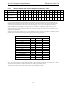
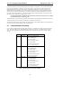
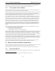
Bit Name Function
2-0 L1B2-L1B0 Modem Line 1 Loopback enable
000 = Disabled (default)
001 = ADC Loopback
010 = Local Analog Loopback
011 = DAC Loopback
100 = Remote Analog Loopback
101 -111 = Vendor optional
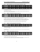
6-4 L2B2-L2B0 Modem Line 2 Loopback enable
000 = Disabled (default)
001 = ADC Loopback
010 = Local Analog Loopback
011 = DAC Loopback
100 = Remote Analog Loopback
101-111 = Vendor optional
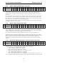
10-8 HSB2-HSB0 Handset Loopback enable
000 = Disabled (default)
001 = ADC Loopback
010 = Local Analog Loopback
011 = DAC Loopback
100 = Remote Analog Loopback
101-111 = Vendor optional
Table 43. Modem Loopback Control Bit Definitions