
Audio Codec '97

AC ‘97 Component Specification Revision 2.3 Rev 1.0
87
7. Power Management
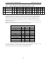
AC ‘97 Codecs can operate at reduced power when no activity is required, and need to be a fully static design, so
that when the clock is stopped the registers will not lose their values. For 2-channel audio Codecs low power states
are controlled by bits D8-D15 in the Powerdown Register, 26h (see Table 29 for full definitions). Monolithic
multichannel Codecs additionally use bits D11-D13 in the Extended Audio Status and Control Register, 2Ah, to
manage their additional DACs. For example, when setting L&R DACs off (PR1) a multichannel audio driver
should also check the Surround, Center and LFE DACs.
Normal
ADCs off
PR0
DACs off
PR1
Digital I/F
off
PR4
PR0=1 PR1=1 PR2=1
Shut off
AC-link
Warm Reset
PR1=0
&
DAC=1
PR0=0
&
ADC=1
Analog
off
PR2 or
PR3
PR4=1
PR2=0
&
ANL=1
Default
Cold Reset
Ready = 1
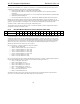
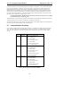
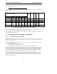
Figure 27. One example of AC ‘97 Powerdown/Powerup flow
Figure 27 illustrates one example procedure to do a complete powerdown of AC ‘97. From normal operation,
sequential writes to the Powerdown Register are performed to powerdown AC ‘97 a subsection at a time. After all
subsections have been shut off, a final write (of PR4) can be executed to shut down the AC ‘97’s digital interface
(AC-link). The part will remain in sleep mode with all its registers holding their static values. To wake-up, the AC
‘97 Controller will send a pulse on the sync line issuing a warm reset. This will restart AC ‘97’s digital interface
(resetting PR4 to zero). AC ‘97 can also be awakened with a cold reset. A cold reset will cause a loss of values of
the registers since this will set them to their default states. When a section is powered back on again, the
Powerdown Control/Status Register (index 26h) should be read to verify that the section is ready (i.e. stable) before
attempting to use it in any operation.
Normal
ADCs off
PR0
DACs off
PR1
Digital I/F
off
PR4
PR0=1 PR1=1 PR4=1
Shut off
AC-link
Warm Reset
PR1=0
&
DAC=1
PR0=0
&
ADC=1
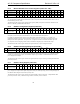
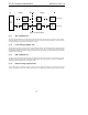
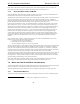
Figure 28. AC ‘97 Powerdown/Powerup flow with analog mixer still alive
Figure 28 illustrates a state when all the analog mixer paths should work with the static volume settings that are
contained in their associated registers. This is used when the user could be playing a CD (or external LINE_IN
source) through AC ‘97 to the speakers but has most of the system in low power mode. The procedure for this