
Audio Codec '97

AC ‘97 Component Specification Revision 2.3 Rev 1.0
94
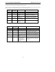
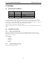
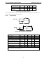
+3.3 Vmain +5 Vmain +12 Vmain +3.3 Vdual (3.3 Vaux)
AC-link (Codec outputs)
• BIT_CLK
• SDATA_IN
9
9
AC-link (contrl. outputs)
• SYNC
• SDATA_OUT
• RESET#
9
9
9
MC’97 digital logic 9
MC’97 analog circuitry 9 (note 1)
Note 1: Modem codecs that do not support hardware capture of caller ID during ACPI S3 or S4 states may alternatively
power their analog circuitry with either 3.3 Vmain or 5 Vmain.
Table 49. Power Distribution: MC ‘97 as the Primary (Modem-Only configuration)
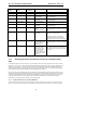
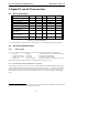
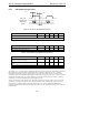
7.5.2 AC ‘97 (Primary) + MC ‘97 (Secondary) Implementations
Table 50 depicts the power distribution that enables both high quality audio and “Off-yet Communicating” modem
operation.
+3.3 Vmain +5V main +5 Vaa from
+12 Vmain
+3.3 Vdual (3.3 Vaux)
AC-link (Codec outputs)
• BIT_CLK
• SDATA_IN(audio)
• SDATA_IN(modem)
9
9
9
AC-link (contr. outputs)
• SYNC
• SDATA_OUT
• RESET#
9
9
9
Audio digital logic 9
Audio analog circuitry 9 (mobile
option)
9
Modem digital logic 9
Modem analog circuitry 9 (note1)
Modem wake logic 9
Note 1: Modem codecs that do not support hardware capture of caller ID during ACPI S3 or S4 states may alternatively
power their analog circuitry with either 3.3 Vmain or 5 Vmain. All audio Codec driven AC-link signals, as well as all other
digital logic associated with the audio subsystem, must be powered by 3.3 Vmain. It is recommended that the audio
subsystem locally regulate +12 Vmain down to +5 Vaa for use by its analog circuitry.
Table 50. Power Distribution: Split Codec Partitioned Audio-plus-Modem
All modem Codec driven AC-link signals, as well as all other digital logic and analog caller ID capture circuitry
must be powered by +3.3 Vdual, enabling an Instantly Available PC.
This power distribution scheme enables the audio Codec to be powered from typical working state voltage sources