
Audio Codec '97

AC ‘97 Component Specification Revision 2.3 Rev 1.0
96
8. Testability
8.1 Activating the Test Modes
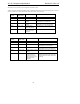
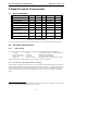
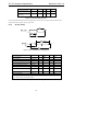
SYNC SDATA_OUT Description
0 0 Normal AC ’97 operation
0 1 ATE Test Mode
1 0 Vendor Test Mode
1 1 Reserved
Table 51. Test Mode Activation
AC ‘97 has two test modes. One is for ATE in circuit test and the other is for vendor-specific tests. All AC-link
signals are normally low through the trailing edge of RESET#. When coming out of RESET, an AC ‘97 Codec
enters the ATE in circuit test mode if SDATA_OUT is sampled high at the trailing edge of RESET#, and enters the
vendor-specific test mode if SYNC is sampled high at the trailing edge of RESET#.
These cases will not occur during typical operating conditions.
Regardless of the test mode, the AC ‘97 Controller must issue a cold reset to resume normal operation of the AC ‘97
Codec.
8.2 Test Mode Functions
8.2.1 ATE in circuit test mode
When AC ‘97 is placed in the ATE test mode, its digital AC-link outputs and digital I/O are driven to a high
impedance state (internal pull-ups for digital I/O pins must be disabled in this mode). This allows ATE in circuit
testing of the AC ‘97 Controller.
Recommended pins:
• BIT_CLK
• SDATA_IN
• EAPD
• SPDIF_OUT
• ID0, ID1
• GPIOs
8.2.2 Vendor-specific test mode
This is left up to the individual vendors.