
Audio Codec '97

AC ‘97 Component Specification Revision 2.3 Rev 1.0
98
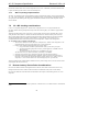
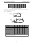
T
rst_low
RESET#
BIT_CLK
T
rst2clk
T
tri2actv
T
tri2actv
SDATA_IN
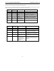
Figure 29. Cold Reset timing diagram when the codec is supplying the BIT_CLK signal
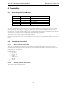
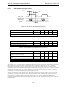
RESET#
BIT_CLK
T
clk2rst
T
tri2actv
SDATA_IN
T
rst_low
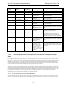
Figure 30 Cold Reset timing diagram when BIT_CLK is being provided by an external source.
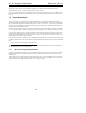
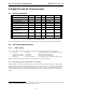
Parameter Symbol Min Typ Max Units
RESET# active low pulse width Trst_low 1.0 - - µs
RESET# inactive to SDATA_IN or
BIT_CLK active delay
Ttri2actv - - 25 ns
RESET# inactive to BIT_CLK startup
delay
Trst2clk 162.8 - 400
18
ns
BITCLK active to RESET# asserted Tclk2rst 0.416 - - µs
Table 53. Cold Reset timing parameters
9.2.1.2
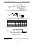
Warm Reset Timing
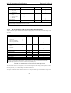
Figure 31. Warm Reset timing diagram
18
Note that this requirement, in combination with the BITCLK startup to Codec Ready Assertion maximum of
400us (defined in section 4.4.1), implies that the first assertion of Codec Ready could be delayed up to 800us after
RESET# deassertion.