
Front Panel I/O Connectivity Design Guide

15
2 Front Panel Legacy I/O
What This Chapter Contains
2.1 Introduction .................................................................................................................. 15
2.2 Switch/LED and IR Connectors.................................................................................... 15
2.3 Front Panel Audio ........................................................................................................ 19
2.1 Introduction
This chapter contains feature descriptions of the signals assigned to the 2x3-pin and 2x5-pin front
panel I/O connectors. This chapter also contains electrical connection information.
This guide does not specify designs for MIDI and diskette drive connectors. These interface types
are stable and well documented. Furthermore, as legacy reduction progresses, the functions of
these connectors will be assumed by newer interfaces such as USB.
CAUTION
Voltages supplied to the front panel connector such as VCC (+5 V) are not overcurrent protected
and should connect only to devices inside the computer’s chassis. Do not use these connectors to
power devices external to the computer’s chassis. A fault in the load presented by an external
device could cause damage to the computer, the interconnecting cable, and the external device
itself. It is strongly recommended that power provided to the external connector shall always
implement overcurrent protection.
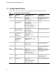
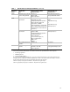
2.2 Switch/LED and IR Connectors
2.2.1 Usage Models
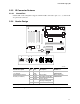
2.2.1.1 Switch/LED Connector
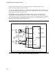
The 2x5-pin front panel connector’s design supports the switch/LED compatibility among multiple
motherboard-chassis combinations. See Figure 1 for header pin layout and function.
2.2.1.2 IR Connector
Figure 1 also shows the 2x3-pin front panel connector’s IrDA
*
feature that supports wireless line-
of-sight peripherals such as remote controls for internal DVD drives, and IR keyboard and mouse
devices.
NOTE
The IrDA connector configuration described here may also be used to support consumer IR.