
Front Panel I/O Connectivity Design Guide

Front Panel I/O Connectivity Design Guide
16
2.2.2 Switch/LED Connector Features
2.2.2.1 Hard Drive Activity LED
Connecting pins 1 and 3 to a front panel mounted LED provides visual indication that data is being
read from or written to the hard drive. For the LED to function properly, an IDE drive should be
connected to the onboard IDE interface. The LED will also show activity for devices connected to
the SCSI (hard drive activity LED) connector.
2.2.2.2 Power / Sleep / Message Waiting LED
Connecting pins 2 and 4 to a single- or dual-color, front panel mounted LED provides power on/off,
sleep, and message waiting indication. Table 2 shows the possible states for a single-color LED.
Table 3 shows the possible states for a dual-color LED.
2.2.2.3 Reset Switch
Supporting the reset function requires connecting pins 5 and 7 to a momentary-contact switch that
is normally open. When the switch is closed, the board resets and runs POST.
2.2.2.4 Power Switch
Supporting the power on/off function requires connecting pins 6 and 8 to a momentary-contact
switch that is normally open. The switch should maintain contact for at least 50 ms to signal the
power supply to switch on or off. The time requirement is due to internal debounce circuitry. After
receiving a power on/off signal, at least two seconds elapses before the power supply recognizes
another on/off signal.
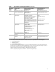
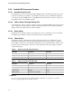
Table 2. States for a Single-Color Power LED
LED State Description ACPI State
Off Sleeping or power off (not running) S1, S3, S5
Steady Green Running S0
Blinking Green Running/message waiting S0
Table 3. States for a Dual-Color Power LED
LED State Description ACPI State
Off Power off S5
Steady Green Running S0
Blinking Green Running/message waiting S0
Steady Yellow Sleeping S1, S3
Blinking Yellow Sleeping/message waiting S1, S3
NOTE
To use the message waiting function, ACPI should be enabled in the operating system and a
message-capturing application should be invoked.