
Front Panel I/O Connectivity Design Guide

Front Panel I/O Connectivity Design Guide
18
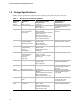
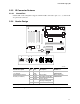
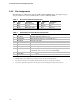
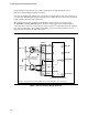
2.2.5 Pin Assignments
The following two tables list the pins for the IR and Switch/LED headers. To support a legacy
2x8-pin connector to connect to both headers, see Note 3 following Table 5.
Table 4. IR Front Panel Electrical Connection
Pin Signal Description Pin Signal Description
1 IRRX2 IrDA serial input 2 GND Ground
3 GND Ground 4 (No pin) Key
5 IRTX2 IrDA serial output 6 +5 V IR power
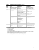
Table 5. Switch/LED Front Panel Electrical Connection
Pin Signal Description
1 HD_LED_P
Hard disk LED pullup (330 Ω) to +5 V
2 FP PWR/SLP
MSG LED pull-up (330 Ω) to +5 V Standby
Note 1
3 HD_LED_N Hard disk active LED
4 FP PWR/SLP
MSG LED pull-up (330 Ω) to +5 V Standby
5 RST_SW_N Reset switch tied to GND
6 PWR_SW_P
Power switch high reference pull-up (2.2 kΩ) to +3.3 V Standby
Note 2
7 RST_SW_P
Reset switch high reference pull-up (1 kΩ to voltage appropriate for the
motherboard circuit, such as, +3.3 V for the ICH bridge)
8 PWR_SW_N Power switch tied to GND
9 RSVD_DNU
Reserved
Note 3
Notes:
1. Standby voltage is the voltage that is active during a sleep state that your board supports.
2. If you want to tie this pin to +5 V Standby, adjust the pull-up resistor size (to 10 kΩ, for example).
3. If you want to support the legacy 2x8 connector, place a 0 ohm shorting resistor between pin 9 and +5 V.