
Front Panel I/O Connectivity Design Guide

Front Panel Legacy I/O
19
2.3 Front Panel Audio
2.3.1 Usage Model
The design options described below support standard front panel microphone and headphone usage
(for Standard AC’97 implementation) and also support new dynamic front panel jack detection and
re-tasking usage models (for Intel
®
High Definition Audio).
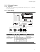
2.3.2 Features
The front panel audio connector is designed to support stereo audio output (headphone or amplified
speakers) and a microphone input. Designs using Intel
®
High Definition Audio (Intel
®
HD Audio)
permit the two front panel jacks to be dynamically reconfigured as input or outputs, depending
upon the desired application.
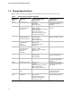
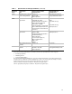
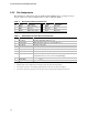
2.3.3 Audio Design Considerations
Front panel audio design in conjunction with motherboard audio header design is dependant upon
the type of audio CODEC being used on the motherboard. In the past, AC’97 Integrated Audio
CODECs were prevalent. With the introduction of Intel High Definition Audio, many new
motherboard designs are switching over to High Definition (HD) audio CODECs. Designers
should note that AC’97 and Intel High Definition Audio front panel motherboards and I/O cards
implementations are different and may not be directly compatible or interchangeable
CAUTION
It is strongly recommended that motherboard designers only use Intel
®
HD Audio analog front
panel dongles with the Intel
®
HD Audio analog front panel header to insure that the jack detection
and dynamic re-tasking capability is preserved. Passive AC’97 analog front panel dongles (ones
which leave the 5V Analog pin-7 line unconnected on the dongle) may be used with the Intel
®
HD
Audio analog front panel header. But note that the front panel jack detection and re-tasking
functionality will be lost as the AC’97 jacks cannot support connection to the SENSE line. In
addition, software must be aware that an AC’97 dongle is being used with an Intel
®
HD Audio
analog header since the software might need to dedicate codec ports that are connected to the
header to meet the product’s intended functionality.
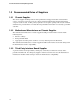
2.3.4 AC’97 Audio
2.3.4.1 AC’97 Audio Electrical Considerations
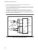
A standard AC’97 front panel audio dongle schematic is shown in Figure 2. The two front panel
audio outputs (FP_OUT_L and FP_OUT_R) send and the two front panel audio returns
(FP_RETURN_L and FP_RETURN_R) connect to a switching-type, 3.5 mm (1/8-inch) ring-tip-
sleeve mini-phone jack mounted on the front panel. The signal path is such that the motherboard
CODEC or output amplifier feeds the front panel jacks via FP_RETURN_L and FP_RETURN_R.
When the front panel jack is not in use, these signals pass through the front panel jack shunt springs
to the back panel jack via the signals FP_RETURN_L and FP_RETURN_R. When headphones are