
Front Panel I/O Connectivity Design Guide

Front Panel I/O Connectivity Design Guide
20
plugged into the front panel jack, these return signals which feed that back panel jack are
disconnected, thus muting the back panel output.
Note that the motherboard should not leave the back panel signal floating when front panel devices
are connected. Permitting the back panel signals to float could result in excessive noise at the back
panel jack when the front panel jack is in use.
The motherboard designer should put weak pull-down resistors (10 k , for example) on the
FP_RETURN_R and FP_RETURN_L lines. If using a single supply for the output amplifier,
ensure that these resistors are located after the output capacitor to avoid loading down the amplifier
bias. The grounded side of these pulldowns should be connected to analog ground to prevent
digital noise from entering the audio sub-system.
MIC
AUD_GND
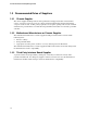
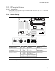
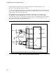
AC’97 Front Panel Dongle Schematic
JACK2 R
JACK2 L
12
34
56
7
910
JACK1 L
MIC BIAS
FP_OUT_R
FP_OUT_L
FP_RETURN_R
FP_RETURN_L
AUD_5V
MIC Jack
Headphone
Jack
JACK1 L
Normally close shunt springs make
contact with the signal path and
cannot be used for Jack detection.
2X5 Stake Pin Header (100mil Pitch)
** Note: Z
L
should be 600Ω or greater @ 100MHz with a low Q (broad Impedance curve over frequency)
EMI Filter
Z
L
**
220pF
220pF
Z
L
**
Z
L
**
Z
L
**
220pF
220pF
AUD_GND
Figure 2. AC’97 Front Panel Dongle Schematic