
Front Panel I/O Connectivity Design Guide


Front Panel Legacy I/O
21
2.3.4.2 AC’97 Audio Header Design
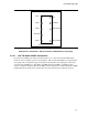
OM10452
2
1
9
10
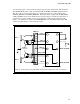
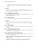
Figure 3. Front Panel Audio Header (Top View)
Manufacturer's Part Number: Wieson Electronic 2100C888-042 (or equivalent)
2.3.4.3 AC’97 Header Pin Assignments
Table 6. AC’97 Front Panel Audio Header Signal Names
Pin Signal Name Description
1 MIC Front panel microphone input signal (biased when supporting stereo
microphone)
2 AUD_GND Ground used by analog audio circuits
3 MIC_BIAS Microphone power / additional MIC input for stereo microphone support
4 AUD_GND Ground used by analog audio circuits
5 FP_OUT_R Right channel audio signal to front panel (headphone drive capable)
6 FP_RETURN_R Right channel audio signal return from front panel (when headphones
unplugged)
7 AUD_5V Filtered +5 V used by analog audio circuits
8 KEY No pin
9 FP_OUT_L Left channel audio signal to front panel (headphone drive capable)
10 FP_RETURN_L Left channel audio signal return from front panel (when headphones unplugged)
2.3.4.4 AC’97 Header Pin Jumpers
The rear panel audio output jacks are disabled when headphones are plugged in. This feature is
implemented through the front panel audio header shown in Figure 3 and Table 6.
If the front panel interface board is not connected to the front panel audio header, jumpers should
be installed across header pin pairs 1-2, 3-4, 5-6, and 9-10. If these jumpers are not installed, the
rear panel line out connector will be inoperative and microphone input pins 1 and 3 will be left
floating, which could lead to elevated back panel microphone noise and cross talk.