
Front Panel I/O Connectivity Design Guide


Front Panel I/O Connectivity Design Guide
24
VREF1_L VREF1_R
HD
CODEC
PORT1 L
PORT1 R
PORT2 R
PORT2 L
SENSE_SEND
GND
PRESENCE#
SENSE1_RETURN
To System GPI
DVDD
JACK2 R
JACK2 L
SENSEVREF2_R VREF2_L
JACK1 L
JACK1 R
Rbias Rbias
Rbias
Rbias
10kΩ
Jack Detection
Network
12
34
56
7
910
C1
C2
C3
C4
Jack Detection Resistors
Rjd_port1**
SENSE2_RETURN
Rjd_port2**
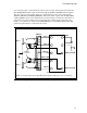
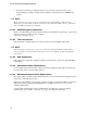
** Values for jack detectiond resistors Rjd_port1 and Rjd_port2 should be chosen based on the which CODEC
ports are connected to header PORT1 and PORT2. See the HD Audio specification for more information on jack
detection resistor value assignment.
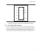
Figure 5. Intel
®
HD Audio Front Panel Analog Header Motherboard Schematic
2.3.5.1.1 Dongle Presence Detection
The PRESENCE# signal is used to inform BIOS that an Intel
®
HD Audio dongle is connect to the
motherboard. This signal should be wired to a system GPI and BIOS should poll the GPI to check
for the presence of the Intel
®
HD Audio dongle in the system during POST. Nominal motherboard
pullup value of 10 k is required on this signal.
2.3.5.1.2 Jack Detection
Jack detection is accomplished with the use of the jack detection resistors Rjd_port1 and Rjd_port2.
The value of these resistors depends on which CODEC ports are tied to the Intel
®
HD Audio analog
header ports. Motherboard designers should consult the Intel
®
HD Audio specification for more
information on the assignment of these values for a give codec port.
2.3.5.2 Intel
®
HD Audio Front Panel Connections
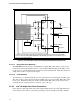
Figure 6 shows a Intel
®
HD Audio front panel dongle implementation and a Intel
®
HD Audio front
panel analog header schematic. The front panel dongle consists of JACK1 and JACK2, and their