
Front Panel I/O Connectivity Design Guide


Front Panel Legacy I/O
25
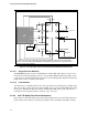
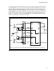
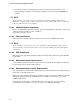
associated signal pins, connected directly to their respective pins on the dongle stake pin header.
The SENSE_SEND signal is split and routed through the PORT1 and PORT2 isolated switches.
The other contact of each isolated switch, are routed to their respective sense return signals,
SENSE1_RETURN and SENSE2_RETURN. This functionality, together with the Rjd_PORT1
and Rjd_PORT2 resistors on the motherboard as shown in Figure 5, informs the audio driver of
jack insertion or removal, which is necessary for dynamic re-taking of the front panel jacks.
Finally, a 1 k pulldown is required on the PRESENCE# pin to signal BIOS that the Intel
®
HD
Audio front panel dongle is connected to the system.
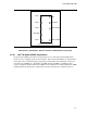
PORT1 L
GND
JACK2 R
JACK2 L
12
34
56
7
910
PORT1 R
PORT2 R
PORT2 L
PRESENCE#
SENSE1_RETURN
SENSE_SEND
1kΩ
JACK 1
JACK 2
Normally Open
Isolated Switch
2X5 Stake Pin Header (100mil Pitch)
SENSE2_RETURN
EMI Filter
Z
L
**
220pF
220pF
Z
L
**
Z
L
**
Z
L
**
220pF
220pF
** Note: Z
L
should be 600Ω or greater @ 100MHz with a low Q (broad Impedance curve over frequency)
Figure 6. Intel
®
HD Audio Front Panel Dongle Implementation