
Front Panel I/O Connectivity Design Guide


Front Panel I/O Connectivity Design Guide
28
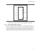
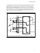
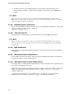
3.2.3 Dual Port USB Header
The Dual Port USB Header consists of a keyed shrouded (Black in color) 2x10 stake pin header
(100-mil pitch) with key locations on pins 9 and 10.
3
4
5 6
7 8
1
2
Figure 7. Dual Port USB Header (Top View)
Manufacturer's Part Number: Wieson Electronic 2120C888-048G (or equivalent) (lead-free)
3.2.4 Dual Port USB Header Pin Assignments
USB ports may be assigned as needed.
Table 8. Dual Port USB Header Pin Assignments
Pin Signal Names Description
1 VREG_FP_USBPWR
Front panel USB power (Ports 0,1) [+5 V or +5 V Dual]
Note
2 VREG_FP_USBPWR Front panel USB power (Ports 0,1) [+5 V or +5 V Dual]
3 USB_FP_P0- Front panel USB Port 0 negative signal
4 USB_FP_P1- Front panel USB Port 1 negative signal
5 USB_FP_P0+ Front panel USB Port 0 positive signal
6 USB_FP_P1+ Front panel USB Port 1 positive signal
7 Ground
8 Ground
9 Key
10 Key
Note: +5 V Dual switches between +5 V and +5V Standby depending on the current board state.
3.2.5 Single Port USB Header
The Single Port USB Header consists of a shrouded (Black in color) 1x5 stake pin header (100-mil
pitch) with key location on pin 5.