
Front Panel I/O Connectivity Design Guide


Front Panel I/O Connectivity Design Guide
42
15
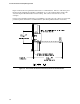
KEY
1
5
Cable
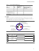
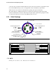
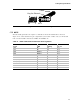
Figure 19. Dual USB Cable Diagram
NOTE
Shrouded stake pin headers are recommended. An un-shrouded header is shown in Figure 19 to
clearly illustrate the pin configuration of the header. Cable connectors P1 should mate to header
numbered as shown in Table 18 and Table 19.
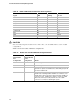
Table 18. Single Port USB Cable and Connector Pin Assignments
Signal AWG Color
PIN
P1 / P2
VREG_FP_USBPWR0 20 -28 Red 1 / 1
USB_FP_P0- 28 White 2 / 2
USB_FP_P0+ 28 White 3 / 3
GROUND 20 - 28 Black 4 / 4
GROUND (Shield) N/A N/A 4 / 4
KEY N/A N/A 5 / 5
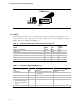
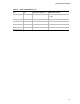
Table 19. Single Port USB Cable Material List
Part Qty
Manufacturer's Part
Number
Note
Material Description
Note
1X5 Header 2 Foxconn JWT: A2541H02-1X5P
(or equivalent)
Header
Key 1 N/A Key
Heat-Shrink Tubing As req. N/A UL Heat-shrink Tube
Shield cable consisting of:
1 28 AWG twisted pairs,
2 20 – 28 AWG discrete
wires
As req. N/A UL Certified Conductor Wire
Part Label 1 N/A Manufacturer's name and P/N
Note: Or equivalent.