
Front Panel I/O Connectivity Design Guide


Cabling Design Guidelines
43
NOTE
Computer systems that have an unshielded cable attached to a USB port may not meet FCC
Class B requirements, even if no device or a low-speed USB device is attached to the cable. Use
shielded cable that meets the requirements for full-speed devices.
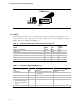
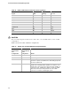
Table 20. USB Cable Recommendations
Characteristic Specification
Flammability Rating UL-94 VW-1
Insulation Resistance 5 k @ 300 VDC
Temperature Range - 55 °C to + 80 °C
Withstand Voltage 1000 VDC @ 60 Hz
Plating Per materials list
Wire Per materials list
Workmanship Parts shall be uniform in workmanship and appearance. There shall be
no excessive nicks, deep scratches, excessive burrs, or defects in
materials that may affect the function, serviceability, or appearance of this
part.
Contact Retention Force Equal to or greater than 2.0 ounces per contact, when unmated from the
proper connector
Maximum Insertion Force 10 pounds per connector
Dimensioning and Tolerances Per ANSI Y14.5M unless otherwise noted on drawing
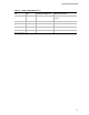
UL Marking The cable manufacturer should supply UL Recognized cables that are
certified under the UL wiring harness program (ZPFW2). The UL
recognition mark should be supplied with the smallest container or bundle
of cables with each shipment.
The UL recognized wire’s insulation will have surface printing identifying
the style, flammability rating, manufacturer’s name, operating voltage and
temperature ratings, along with the UL recognition mark.
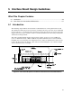
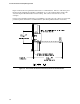
4.5 IEEE1394 Cabling (Motherboard to I/O Interface Board)
4.5.1 Introduction
This chapter provides some details of the design for a front panel IEEE 1394 interface cable to be
used in conjunction with the front panel I/O interface board and main board. The interface cable
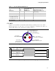
must be shielded as specified in Figure 20 for two reasons:
• To ensure the cable data lines meet the required differential characteristic impedance as given
in the IEEE 1394 specification. Cables with an impedance variation outside of the IEEE 1394
specification limits will degrade signal quality and could cause front panel IEEE 1394 devices
to fail to operate reliably.
• To shield the cable from RF emissions inside the chassis. Improperly shielded interface cables
can pick up these internally radiated signals and cause the system to fail EMI testing.
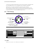
Figure 22 shows the recommended IEEE 1394A/B interface cable details and pin assignments. Pin
assignments are further detailed in Table 21 and Table 22. The cable materials (including