
Front Panel I/O Connectivity Design Guide


Front Panel I/O Connectivity Design Guide
44
connectors) and construction should enable the system to meet the performance requirements of the
most current IEEE 1394 Specification and applicable safety and regulatory requirements.
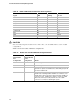
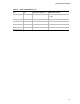
Table 24 shows some current recommendations regarding cable parts and materials.
The cable length (in combination with the trace lengths on the main board and front panel I/O
interface board) must be such that it will satisfy the signal quality requirements (propagation delay,
etc.) given in the most recent version of the IEEE 1394 Specification.
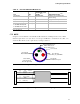
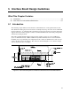
4.5.2 Cable Drawings
7, 8: +12V
Cover Jacket
Inner Shield:
Aluminum Metalized
Polyester
Shield:
> 65% Interwoven
Tinned Copper Braid
Twisted Signaling Pair B:
5: TPB+
6: TPB-
Twisted Signaling Pair A:
1: TPA+
2: TPA-
Terminated in one contact
10, Outer Shield
3: Pair A Shield
4: Pair B Shield
Figure 20. Single Port IEEE 1394A/B Cable Cross Section
KEY
20
20
26/28
26/28
26/28
26/28
AWG
1
8
6
5
2
P1
7
3
4
10
9
P2
7
4
1
2
8
5
6
20
3
20
GND
GND
GND
GND
GND
GND
GND
10
GND
Signal
+12V
+12V
TPB+
TPB-
TPA+
TPA-
Signal
+12V
+12V
TPB+
TPB-
TPA+
TPA-
KEY 9
A
B
10 10
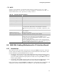
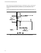
Figure 21. IEEE 1394A/B Cable Wiring Diagram
NOTE
Drawings are not shown to scale. Dimensions are in millimeters.