
Front Panel I/O Connectivity Design Guide


Cabling Design Guidelines
45
1
210
9
KEY
19
10
2
Cable
Key for Shroud
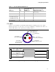
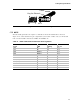
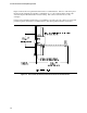
Figure 22. IEEE 1394A/B Cable Diagram
NOTE
Shrouded stake pin headers are highly recommended. An un-shrouded header is shown in
Figure 22 to clearly illustrate the pin configuration of the header. Cable connectors P1 should
mate to header numbered as shown in Table 21 and Table 22.
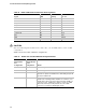
Table 21. IEEE 1394A Cable and Connector Pin Assignments
Signal AWG Pairing
PIN
P1 / P2
TPA+ 28 A 1 /1
TPA- 28 A 2 /2
GND SHIELD 3 /3
GND SHIELD 4 / 4
TPB+ 28 B 5 / 5
TPB- 28 B 6 /6
+12V(Fused) 20 7 /7
+12V(Fused) 20 8 /8
KEY N/A 9/9
GND 20 10/10
GND SHIELD 10/10