
Front Panel I/O Connectivity Design Guide


Front Panel I/O Connectivity Design Guide
46
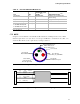
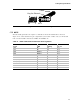
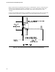
Table 22. IEEE 1394B Cable and Connector Pin Assignments
Signal AWG Pairing
PIN
P1 / P2
TPA+ 28 A 1 /1
TPA- 28 A 2 /2
TPA_REF SHIELD 3 /3
TPB_REF SHIELD 4 / 4
TPB+ 28 B 5 / 5
TPB- 28 B 6 /6
+12V(Fused) 20 7 /7
+12V(Fused) 20 8 /8
KEY N/A 9/9
GND 20 10/10
GND SHIELD 10/10
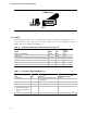
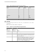
CAUTION
Since the 1394 front panel headers are keyed the same, care should be taken to ensure a valid
configuration.
Table 23 shows the results of different configurations.
Table 23. Header Port to Cable I/O Board Configuration Chart
1394 Front
Panel Header
Port
Configuration
1394 Front
Panel Cable I/O
Board
Configuration
Result
1394A 1394A Valid Configuration
1394B 1394B Valid Configuration
1394A 1394B INVALID CONFIGURATION. 1394B devices with a Beta-only
port will not operate and 1394B devices with a Bilingual port will
operate in 1394A mode.
1394B 1394A INVALID CONFIGURATION. 1394A devices will operate in
1394A mode if a Bilingual Mode 1394B host controller is used.
1394A devices will not operate if a Beta-only Mode 1394B host
controller is used. 1394B devices will try to operate in 1394B
Beta mode, but may have link problems since the 1394A
connector is not rated for 1394B signal speeds.