
Front Panel I/O Connectivity Design Guide


49
5 Interface Board Design Guidelines
What This Chapter Contains
5.1 Introduction .................................................................................................................. 49
5.2 Front Panel I/O Interface Board Dimensions ............................................................... 51
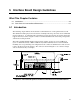
5.1 Introduction
The following chapter defines the mechanical recommendations of a front-panel interface board.
The definition includes physical raw board size, mounting holes, keep-out zones and recommended
physical tolerances. A compliant front panel interface board can be used in any chassis design that
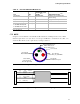
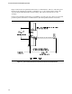
supports these key features. Figure 23 shows recommended dimensions of the front panel aperture
and interface board placement.
The front panel I/O guideline defines an I/O aperture opening area that is 3.875+/- 0.008 inch
(98.43 +/- 0.20 mm) wide by 1.000 +/- 0.008 inch (25.40+/- 0.20 mm) tall. To retain maximum
flexibility, the exact positioning and configuration of the connectors within the I/O connector zone
is left to the discretion of the designer. The connectors shown in Figure 23 are a reference design
and are shown here only as examples.
Figure 23. Front Panel I/O Aperture and Interface Board Placement Recommendations