
Front Panel I/O Connectivity Design Guide
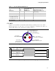


Front Panel I/O Connectivity Design Guide
50
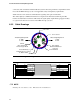
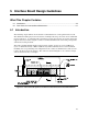
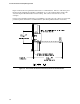
Figure 24 shows the front panel I/O board interface recommendations. The face of the front panel
I/O board edge should be placed 0.053 +/- 0.010 inch (1.35 +/- 0.25 mm) from the inside of the
chassis front panel I/O shield and/or chassis housing. The connectors shown here are only
examples.
It is the front panel I/O board designer’s responsibility to properly place the connector to meet front
panel I/O aperture and interface recommendations. (The front panel I/O shield is not shown.)
Figure 24. Front Panel I/O Interface Board Placement Recommendations