
Front Panel I/O Connectivity Design Guide


53
6 Chassis and I/O Shield Guidelines
What This Chapter Contains
6.1 Introduction .................................................................................................................. 53
6.2 Front Panel I/O Board Placement ................................................................................ 53
6.3 Front Panel I/O Reference Designs ............................................................................. 56
6.1 Introduction
This chapter defines the chassis and I/O shield mechanical guidelines for the front panel I/O
interface. Typical chassis interfaces should adhere to the definitions of the front panel I/O board’s
keep-out zones, and mounting hole recommendations. Compliant front panel chassis interface
boards can be used in any chassis design that supports these key features.
Beyond the specific aperture opening and keep-out zones, the chassis and bezel implementation of
the front panel I/O board is not limited to specific features or locations.
NOTE
Figure 23 and Figure 24 are repeated as Figure 27 and Figure 28 in this chapter for convenience
only.
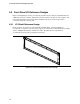
6.2 Front Panel I/O Board Placement
The exact location of the front panel I/O board is not specified. It is recommended that it be placed
in the front of the system in either a horizontal or a vertical orientation. When placing the front
panel I/O board, the designer should consider that the proper clearance should be provided for the
chassis peripheral bays and motherboard keepout recommendations. The system designer should
also take into consideration impact to system front airflow, venting, and full-length add-in board
retention features.
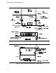
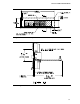
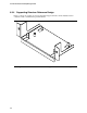
As shown in Figure 27, the bottom of the front panel opening is located 0.045 to 0.055 inches (1.15
to 1.39 mm) below the bottom of a typical, 0.062 inches (1.57 mm) thick board. Also, a 0.1 inches
(2.54 mm) minimum keepout zone has been defined around the perimeter of the aperture area, on
both inside and outside surfaces of the chassis front panel. The keepout zone provides a reserved
space that can be used to attach a chassis-independent front I/O shield into the chassis front panel.
No slots, tabs, notches, or other topographical features should be placed within the keepout zone.
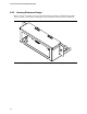
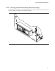
Interface board connector placement should be limited as shown in Figure 27 and Figure 28 to
allow enough clearance between the connectors and the chassis opening for the I/O shield.