
Front Panel I/O Connectivity Design Guide


Front Panel I/O Connectivity Design Guide
64
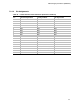
7.2.2 Pin Assignments
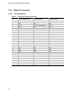
Table 25. Serial-WHQL Debug Connector
Pin Signal Name
1 DCD (Data Carrier Detect)
2 DSR (Data Set Ready)
3 SIN # (Serial Data In)
4 RTS (Request to Send)
5 SOUT # (Serial Data Out)
6 CTS (Clear to Send)
7 DTR (Data Terminal Ready)
8 RI (Ring Indicator)
9 Ground
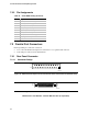
7.3 Parallel Port Connectors
Internal parallel port connection consists of:
• A 25-contact motherboard footprint for connection to a rear panel D-sub connector
• A 26 stake-pin connector on the motherboard
7.3.1 Rear Panel Connector
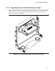
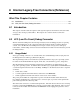
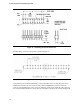
7.3.1.1 Connector Design
OM12198
1
14
13
25
Figure 36. Motherboard Footprint for the Parallel Port Rear Panel Connector (Bottom View)
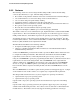
OM12199
1
14
13
25
Figure 37. Parallel Port Rear Panel Connector (Outside View)
Manufacturer's Part Number: Foxconn DM11351-PR1 (or equivalent)