
Front Panel I/O Connectivity Design Guide


67
8 Internal Legacy-Free Connectors (Reference)
What This Chapter Contains
8.1 Introduction .................................................................................................................. 67
8.2 LPC (Low Pin Count) Debug Connector ...................................................................... 67
8.1 Introduction
This chapter contains feature descriptions of the signals assigned to the internal connectors found
on legacy-free and legacy-reduced PC’s. This chapter also contains electrical connection
information.
8.2 LPC (Low Pin Count) Debug Connector
The PC-AT serial COM port has been used previously by low level debuggers (such as operating
system kernel debuggers) as the connection point between the PC under test and the debugger
console. Since the PC-AT serial COM port is no longer a feature on legacy-free and legacy-
reduced PCs, an LPC debug connector has been introduced for inclusion on main boards to provide
the debug interface.
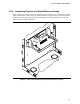
8.2.1 Usage Model
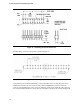
Two types of debug connectors are considered here: the standard Debug Connector (16 pins) and
the Debug Connector with Legacy Extension (20 pins).
The 16-pin Debug Connector is intended for systems that will run a legacy-free operating system.
It consists of the minimum LPC bus signals, an I2C bus, a mechanical key, power, and ground.
The 20-pin Debug Connector with Legacy Extension is intended for use with both legacy and
legacy-free operating systems. It adds the 8042 controller legacy signals (RC# and A20GATE) and
a serial interrupt line which is used to route IRQ1 and IRQ12 to the main board. Power is required
as follows:
• 5 VDC and 3.3 VDC
• 3.3 VDC (required for the LPC interface and for the serial EEPROM)
• 5 VDC (required for the RS-232C drivers and receivers on the module)
The power pins should be de-coupled with capacitors on both the module and the main board.
De-coupling should take place at their respective connectors pins, to provide an AC signal return
path for the signals in the connecting cable.
The main board connector is a non-shrouded pin header. The main board connector uses a missing
pin at the position labeled KEYWAY to guarantee proper module cable alignment. The receptacle
connector on the module cable should have the KEYWAY location plugged to guarantee correct
installation.