
Front Panel I/O Connectivity Design Guide

Front Panel I/O Connectivity Design Guide
68
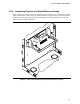
8.2.2 Features
The following criteria were used to design the LPC debug module of which the LPC debug
connector (described here) is a part. The LPC debug module is to:
• Be available on all production hardware which does not include the PC-AT serial COM port
• Use standard interfaces to connect the debug console to the PC under test
• Use a no-silicon design for quick industry enabling
• Not limit the hardware configurations of the PC system under test
• Minimize the processor and memory overhead of the debug data stream of the PC under test
• Be a private resource for the operating system
• Be easily discovered and enumerated by the operating system
• Support one full duplex 57,600 bits per second serial data pipe (minimum)
The module consists of a serial communications port, implemented with a standard 16550 UART
register interface. The serial communications port registers are not allowed to appear at a legacy
COM port I/O addresses, and should be reported to the operating system using a new ACPI table.
To minimize the impact to the main board, the module interface is placed on the Intel
®
Low Pin
Controller (LPC) interface. Since no LPC 16550 UART is available commercially, an LPC Super
I/O device (SIO) should be used to implement the module.
The LPC SIO used should have the following attributes:
• Its registers should be plug and play compatible
• All legacy controllers (including the 8042) and interfaces in the SIO should be hardware
disabled following a PCI reset.
An I2C serial EEPROM is provided on the module to provide the BIOS with the information used
to configure the COM port in the SIO. This information and method is detailed in the BIOS
requirements section of the Intel
®
LPC Debug Module Requirements Specification (v1.0).
Using the serial EEPROM to specify the programming method allows any SIO that meets the above
requirements to be used on the debug module. The serial EEPROM can be assigned the I2C
addresses: 1010111xb – 1010100xb by the main board. Since only eight, I2C serial EEPROM
devices can occupy one SMBUS segment, system designers should insure there is no conflict
between the I2C address assigned to the debug module and other Serial EPROM devices in the
system.
The serial EEPROM device should be capable of being written for field upgrade support. A jumper
on the module for write-enable control is an acceptable way to implement this requirement.
The debug module is defined in such a way that it supports two operating environments:
• Operation with a legacy-free operating system
• Operation with a legacy operating system
Operation with a legacy-free operating system is the intended mode of operation of the Debug
module.
Operation with a legacy operating system may be required to support legacy-free early design
validation and manufacturing test flows. Two connector sizes are therefore recommended for the
module interface. The smaller connector only supports the debug port function. The larger