
Front Panel I/O Connectivity Design Guide


Internal Legacy-Free Connectors (Reference)
69
connector supports the signals needed to have full 8042 controller support: RC#, A20GATE, and
SERIRQ.
NOTE
Legacy operation should only be enabled for operation with a legacy operating system. This means
a BIOS setup option needs to be supported which turns legacy mode on and off. In legacy
operation mode, a PS/2
*
Keyboard and mouse would need to be attached to the debug module since
a legacy-free BIOS is not required to provide USB legacy keyboard emulation. In addition, when
operating the module in legacy mode, the COM port should be programmed by the BIOS to operate
as COM1.
A null modem cable is required to connect the debug module to the serial port on another PC. The
debug module uses a DB9-male connector that is wired in the standard way for a PC serial COM
port.
8.2.3 Header Design
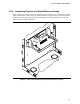
8.2.3.1 Module to Motherboard Mechanical Interface
The only mechanical connection between the debug module and the main board is the LPC debug
connector. No mechanical guides or retention hardware are required.
8.2.3.2 LPC Debug Connector
The LPC debug connector for desktop systems is a vertical 0.1 inches x 0.1 inches stake-pin header
with 16 or 20 pins. Pin 4 is voided to allow keying with the mating cable. The pins are 0.025-inch
square posts or a round post with equivalent dimensioning as shown in Table 28.
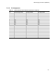
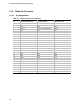
Table 28. LPC Debug Connector Features
Connector Header Parameter “A” (inches) Number of Circuits
Manufacturer's Part
Number
Note
Debug 0.70 16 N/A
Legacy Extension 0.90 20 Molex 0870892016
Note: Or equivalent
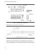
The LPC debug connector’s physical dimensions are specified in Figure 38.