Intel® Desktop Board DQ57TML Technical Product Specification June 2010 Order Number: E98643-001US The Intel® Desktop Board DQ57TML may contain design defects or errors known as errata that may cause the product to deviate from published specifications. Current characterized errata are documented in the Intel Desktop Board DQ57TML Specification Update.
Revision History Revision -001 Revision History Date ® First release of the Intel Desktop Board DQ57TML Technical Product Specification June 2010 This product specification applies to only the standard Intel® Desktop Board DQ57TML with BIOS identifier TMIBX10H.86A. Changes to this specification will be published in the Intel Desktop Board DQ57TML Specification Update before being incorporated into a revision of this document. INFORMATION IN THIS DOCUMENT IS PROVIDED IN CONNECTION WITH INTEL® PRODUCTS.
Preface This Technical Product Specification (TPS) specifies the board layout, components, connectors, power and environmental requirements, and the BIOS for the Intel® Desktop Board DQ57TML. Intended Audience The TPS is intended to provide detailed, technical information about the Intel Desktop Board DQ57TML and its components to the vendors, system integrators, and other engineers and technicians who need this level of information. It is specifically not intended for general audiences.
Intel Desktop Board DQ57TML Technical Product Specification Other Common Notation iv # Used after a signal name to identify an active-low signal (such as USBP0#) GB Gigabyte (1,073,741,824 bytes) GB/s Gigabytes per second Gb/s Gigabits per second KB Kilobyte (1024 bytes) Kbit Kilobit (1024 bits) kbits/s 1000 bits per second MB Megabyte (1,048,576 bytes) MB/s Megabytes per second Mbit Megabit (1,048,576 bits) Mbits/s Megabits per second xxh An address or data value ending with a low
Contents 1 Product Description 1.1 Overview.......................................................................................... 9 1.1.1 Feature Summary .................................................................. 9 1.1.2 Board Layout ....................................................................... 11 1.1.3 Block Diagram ..................................................................... 13 1.2 Legacy Considerations......................................................................
Intel Desktop Board DQ57TML Technical Product Specification 2.4 Intel® Management Engine BIOS Extension (Intel® MEBx) Reset Header .................................................................................. 2.5 Mechanical Considerations ................................................................ 2.5.1 Form Factor......................................................................... 2.6 Electrical Considerations ................................................................... 2.6.
Contents Figures 1. 2. 3. 4. 5. 6. 7. 8. 9. 10. 11. 12. 13. 14. 15. 16. 17. Major Board Components.................................................................. 11 Block Diagram ................................................................................ 13 Memory Channel and DIMM Configuration ........................................... 17 Back Panel Audio Connectors ............................................................ 22 LAN Connector LED Locations .......................................
Intel Desktop Board DQ57TML Technical Product Specification 27. 28. 29. 30. 31. 32. 33. 34. 35. 36. 37. 38. 39. 40. 41. 42. 43. 44. 45. 46. 47. 48. 49. 50. 51. viii Main Power Connector...................................................................... Front Panel Header .......................................................................... States for a One-Color Power LED ...................................................... Alternate Front Panel Power LED Header ................................
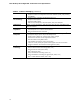
1 Product Description 1.1 Overview 1.1.1 Feature Summary Table 1 summarizes the major features of the board. Table 1. Feature Summary Form Factor MicroATX (9.60 inches by 9.60 inches [243.84 millimeters by 243.
Intel Desktop Board DQ57TML Technical Product Specification Table 1. Feature Summary (continued) BIOS • Intel® BIOS resident in the SPI Flash device • Support for Advanced Configuration and Power Interface (ACPI), Plug and Play, and SMBIOS Instantly Available PC Technology • Support for PCI* Local Bus Specification Revision 2.
Product Description 1.1.2 Board Layout Figure 1 shows the location of the major components on Intel Desktop Board DQ57TML. Figure 1. Major Board Components Table 2 lists the components identified in Figure 1.
Intel Desktop Board DQ57TML Technical Product Specification Table 2.
Product Description 1.1.3 Block Diagram Figure 2 is a block diagram of the major functional areas of the board. Figure 2.
Intel Desktop Board DQ57TML Technical Product Specification 1.2 Legacy Considerations This board differs from other Intel Desktop Board products, with specific changes including (but not limited to) the following: • 1.3 1.4 No Parallel ATA (PATA) IDE drive connector Online Support To find information about… Visit this World Wide Web site: Intel Desktop Board DQ57TML http://www.intel.com/products/desktop/motherboards/DQ57TML/DQ 57TML-overview.htm Desktop Board Support http://www.intel.
Product Description Intel® Q57 Express Chipset 1.5 The Intel Q57 Express Chipset consisting of the Intel Q57 Platform Controller Hub (PCH) provides interfaces to the processor and the USB, SATA, LPC, audio, network, display, Conventional PCI, and PCI Express x1 interfaces. The PCH is a centralized controller for the board’s I/O paths. For information about Refer to The Intel Q57 Express chipset http://www.intel.com/products/desktop/chipsets/index.htm Resources used by the chipset Chapter 2 1.
Intel Desktop Board DQ57TML Technical Product Specification For information about… Refer to: Tested Memory http://www.intel.com/support/motherboards/desktop/sb/CS025414.htm 1.6.1 Memory Configurations The Intel Core i7, Intel Core i5, Intel Core i3, Intel Pentium processors, and Intel Xeon processors 3400 series support the following types of memory organization: • • 16 Dual channel (Interleaved) mode. This mode offers the highest throughput for real world applications.
Product Description Figure 3 illustrates the memory channel and DIMM configuration. Figure 3. Memory Channel and DIMM Configuration NOTE When using a processor without Intel Graphics Technology, there must always be memory installed into any or both of the DIMM 0 (blue) memory sockets for the system to boot.
Intel Desktop Board DQ57TML Technical Product Specification 1.7 Graphics Subsystem The board supports system graphics through either Intel Graphics Technology or a PCI Express 2.0 x16 add-in graphics card. 1.7.1 Integrated Graphics The board supports integrated graphics through the Intel® Flexible Display Interface (Intel® FDI) for processors with Intel Graphics Technology. 1.7.1.1 Analog Display (VGA) The VGA port supports analog displays.
Product Description 1.8 USB The board supports up to twelve USB 2.0 ports through two EHCI host controllers on the PCH that allow the use of EHCI-compatible drivers.
Intel Desktop Board DQ57TML Technical Product Specification 1.9.1.2 Intel® Rapid Recover Technology The board incorporates the Intel® Rapid Recover Technology (Intel® RRT). Intel Rapid Recover Technology is a feature of Intel Rapid Storage Technology. It uses RAID 1 (mirroring) functionality to copy data from a designated master drive to a designated recovery drive. The master drive data can be copied to the recovery drive either continuously or on request.
Product Description 1.11 Audio Subsystem The board supports Intel High Definition Audio through the Realtek ALC662-VC audio codec. The Realtek ALC662-VC-based audio subsystem supports the following features: • • • • • • 6-channel audio with independent multi-streaming stereo. Advanced jack sense for the back panel audio jacks that enables the audio codec to recognize the device that is connected to an audio port.
Intel Desktop Board DQ57TML Technical Product Specification 1.11.2 Audio Headers and Connectors The board contains audio connectors and headers on both the back panel and the component side of the board.
Product Description 1.11.2.2 S/PDIF Header The S/PDIF header allows connections to coaxial or optical dongles for digital audio output. 1.11.2.3 Internal Mono Speaker Header The internal mono speaker header allows connection to an internal, low-power speaker for basic system sound capability. The subsystem is capable of driving a speaker load of 8 Ohms at 1 W (rms) or 4 Ohms at 1.5 W (rms). 1.
Intel Desktop Board DQ57TML Technical Product Specification 1.12.3 RJ-45 LAN Connector with Integrated LEDs Two LEDs are built into the RJ-45 LAN connector (shown in Figure 5). Item Description A Link/Activity LED (green) B Link Speed LED (green/yellow) Figure 5. LAN Connector LED Locations Table 5 describes the LED states when the board is powered up and the LAN subsystem is operating. Table 5.
Product Description 1.13 Real-Time Clock Subsystem A coin-cell battery (CR2032) powers the real-time clock and CMOS memory. When the computer is not plugged into a wall socket, the battery has an estimated life of three years. When the computer is plugged in, the standby current from the power supply extends the life of the battery. The clock is accurate to ± 13 minutes/year at 25 ºC with power applied through the power supply 5V STBY rail.
Intel Desktop Board DQ57TML Technical Product Specification 1.14 Thermal Monitoring Figure 6 shows the locations of the thermal sensors and fan headers. Item Description A Rear chassis fan header B Thermal diode, located on processor die C Processor fan header D Front chassis fan header Figure 6.
Product Description 1.15 Platform Management and Security In addition to Intel AMT the Intel DQ57TML Desktop Board integrates several functions designed to manage the system and lower the total cost of ownership (TCO) of the system. These system management functions are designed to report errors, diagnose the system, and recover from system lockups without the aid of an external microcontroller. 1.15.
Intel Desktop Board DQ57TML Technical Product Specification 1.15.2 Intel® vPro™ Technology Intel® vPro™ Technology is a set of processor and platform capabilities designed to enable greater proactive security, enhanced maintenance, and improved remote management both inside and outside the corporate firewall.
Product Description • Remote troubleshooting and recovery that can significantly reduce desk-side visits and potentially increasing efficiency of IT technical staff. ⎯ System event log ⎯ IDE Redirection (IDE-R) or PXE boot: remote CD or network drive boot ⎯ Serial over LAN ⎯ OOB diagnostics ⎯ Remote control • ⎯ Operating system repair Proactive alerting that decreases downtime and minimizes time to repair.
Intel Desktop Board DQ57TML Technical Product Specification • KVM (Keyboard-Video-Mouse) Redirection allows an IT administrator to remotely control a user’s keyboard without having to rely on third-party software applications. The user retains the ability to allow or discontinue the remote access through on-screen pop-up windows. NOTE KVM Redirection requires the use of an Intel® processor with integrated graphics.
Product Description 1.15.2.1.3 Intel ME “M” State LED The board has a red-colored Intel ME “M” state LED (see Figure 7). The “M” state is based on Intel ME status, as follows: • • • M0 = Intel ME is in full control in S0 M3 = Intel ME is in full control in S3-S5 for “out of band” Intel manageability Moff = Intel ME is in sleep state after Intel ME timeout has occurred Table 6 shows expected behavior of the “M” state LED. Table 6.
Intel Desktop Board DQ57TML Technical Product Specification 1.15.2.2 Intel® Virtualization Technology (Intel® VT) Intel Virtualization Technology (Intel VT) is a processor technology that enables a platform to run multiple operating systems and applications as independent machines, allowing one computer system to function as multiple "virtual" systems.
Product Description Inside the firewall, this feature adapts Client Initiated Local Access (CILA); outside the firewall it uses Client Initiated Remote Access (CIRA). This service is triggered in the same manner as Intel RPAT. Many of the features of Intel AMT are available with Intel RPAT and Intel Fast Call for Help. These include Serial-over-LAN, IDE Redirection, KVM Redirection and PC Alarm Clock.
Intel Desktop Board DQ57TML Technical Product Specification 1.16 Power Management Power management is implemented at several levels, including: • • Software support through Advanced Configuration and Power Interface (ACPI) Hardware support: ⎯ Power connector ⎯ Fan headers ⎯ LAN wake capabilities ⎯ Instantly Available PC technology ⎯ Wake from USB ⎯ Power Management Event signal (PME#) wake-up support ⎯ PCI Express WAKE# signal support ⎯ Wake from serial port 1.16.
Product Description 1.16.1.1 System States and Power States Under ACPI, the operating system directs all system and device power state transitions. The operating system puts devices in and out of low-power states based on user preferences and knowledge of how devices are being used by applications. Devices that are not being used can be turned off. The operating system uses information from applications and user settings to put the system as a whole into a low-power state.
Intel Desktop Board DQ57TML Technical Product Specification 1.16.1.2 Wake-up Devices and Events Table 9 lists the devices or specific events that can wake the computer from specific states. Table 9.
Product Description 1.16.2 Hardware Support CAUTION Ensure that the power supply provides adequate +5 V standby current if LAN wake capabilities and Instantly Available PC technology features are used. Failure to do so can damage the power supply. The total amount of standby current required depends on the wake devices supported and manufacturing options.
Intel Desktop Board DQ57TML Technical Product Specification 1.16.2.
Product Description 1.16.2.4 Instantly Available PC Technology CAUTION For Instantly Available PC technology, the +5 V standby line for the power supply must be capable of providing adequate +5 V standby current. Failure to provide adequate standby current when implementing Instantly Available PC technology can damage the power supply. Instantly Available PC technology enables the board to enter the ACPI S3 (Suspend-toRAM) sleep-state.
Intel Desktop Board DQ57TML Technical Product Specification 1.16.2.9 +5 V Standby Power LED The green +5 V standby power indicator LED shows that power is still present even when the computer appears to be off. Figure 8 shows the location of the Standby Power indicator LED on the board. CAUTION If AC power has been switched off and the standby power indicators are still lit, disconnect the power cord before installing or removing any devices connected to the board.
2 Technical Reference 2.1 Memory Resources 2.1.1 Addressable Memory The board utilizes 16 GB of addressable system memory. Typically the address space that is allocated for PCI Conventional bus add-in cards, PCI Express configuration space, BIOS (SPI Flash device), and chipset overhead resides above the top of DRAM (total system memory).
Intel Desktop Board DQ57TML Technical Product Specification Figure 9.
Technical Reference 2.1.2 Memory Map Table 10 lists the system memory map. Table 10. System Memory Map Address Range (decimal) Address Range (hex) Size Description 1024 K - 16777216 K 100000 - 3FFFFFFFF 16382 MB Extended memory 960 K - 1024 K F0000 - FFFFF 64 KB Runtime BIOS 896 K - 960 K E0000 - EFFFF 64 KB Reserved 800 K - 896 K C8000 - DFFFF 96 KB Potential available high DOS memory (open to the PCI Conventional bus). Dependent on video adapter used.
Intel Desktop Board DQ57TML Technical Product Specification 2.2.1 Back Panel Connectors Figure 10 shows the location of the back panel connectors for the board. Item Description A B C D E F G H I J PS/2 keyboard/mouse port USB ports VGA output Parallel port DVI-D output LAN USB ports Audio line in Mic in Audio line out Figure 10. Back Panel Connectors NOTE The back panel audio line out connector is designed to power headphones or amplified speakers only.
Technical Reference 2.2.2 Component-side Connectors and Headers Figure 11 shows the locations of the component-side connectors and headers. Figure 11. Component-side Connectors and Headers Table 11 lists the component-side connectors and headers identified in Figure 11.
Intel Desktop Board DQ57TML Technical Product Specification Table 11.
Technical Reference 2.2.2.1 Signal Tables for the Connectors and Headers Table 12. Serial Port Header Pin Signal Name Pin Signal Name 1 DCD (Data Carrier Detect) 2 RXD# (Receive Data) 3 TXD# (Transmit Data) 4 DTR (Data Terminal Ready) 5 Ground 6 DSR (Data Set Ready) 7 RTS (Request To Send) 8 CTS (Clear To Send) 9 RI (Ring Indicator) 10 Key (no pin) Table 13.
Intel Desktop Board DQ57TML Technical Product Specification Table 14. S/PDIF Header Pin Signal Name 1 Ground 2 S/PDIF out 3 Key (no pin) 3 +5V_DC Table 15. Internal Mono Speaker Header Pin Signal Name 1 − 2 + Table 16.
Technical Reference Table 18. Front Panel Audio Header for AC ’97 Audio Pin Signal Name Pin Signal Name 1 MIC 2 AUD_GND 3 MIC_BIAS 4 AUD_GND 5 FP_OUT_R 6 FP_RETURN_R 7 AUD_5V 8 KEY (no pin) 9 FP_OUT_L 10 FP_RETURN_L Note: Not all AC ’97 signals are supported; specifically, pins 4, 6, 7, and 10 are not supported. Table 19.
Intel Desktop Board DQ57TML Technical Product Specification Table 21. Chassis Intrusion Header Pin Signal Name 1 Intruder# 2 Ground Table 22. Processor (4-Pin) Fan Header Pin Signal Name 1 Ground 2 +12 V 3 FAN_TACH 4 FAN_CONTROL Table 23. Front and Rear Chassis Fan Headers Pin 4-Wire Support Pin 3-Wire Support 1 Ground 3 Ground 2 +12 V 2 FAN_POWER 3 FAN_TACH 1 FAN_TACH 4 FAN_CONTROL N/A N/A Table 24.
Technical Reference Table 25.
Intel Desktop Board DQ57TML Technical Product Specification 2.2.2.2 Add-in Card Connectors The board has the following add-in card connectors: • • • One PCI Express 2.0 x16: this connector supports simultaneous transfer speeds of up to 8 GB/s of peak bandwidth per direction. Two PCI Express 2.0 x1: each of these connectors support simultaneous transfer speeds of up to 500 MB/s of peak bandwidth per direction. One Conventional PCI (rev 2.3 compliant) connector.
Technical Reference Table 27. Main Power Connector Pin Signal Name Pin 1 +3.3 V 13 +3.3 V 2 +3.3 V 14 −12 V 3 Ground 15 Ground 4 +5 V 16 PS-ON# (power supply remote on/off) 5 Ground 17 Ground 6 +5 V 18 Ground 7 Ground 19 Ground 8 PWRGD (Power Good) 20 −5 V (obsolete) 9 +5 V (Standby) 21 +5 V 10 +12 V 22 +5 V 11 +12 V (Note) 23 +5 V (Note) 12 +3.
Intel Desktop Board DQ57TML Technical Product Specification 2.2.2.4 Front Panel Header This section describes the functions of the front panel header. Table 28 lists the signal names of the front panel header. Figure 12 is a connection diagram for the front panel header. Table 28.
Technical Reference 2.2.2.4.1 Hard Drive Activity LED Header Pins 1 and 3 can be connected to an LED to provide a visual indicator that data is being read from or written to a hard drive. Proper LED function requires one of the following: • • • SATA storage device connected to an onboard SATA connector PATA storage device connected to the onboard PATA connector Intel Z-U130 USB Solid State Drive (or compatible device) connected to one of the front panel USB headers 2.2.2.4.
Intel Desktop Board DQ57TML Technical Product Specification 2.2.2.6 Front Panel USB Headers Figure 13 is a connection diagram for the front panel USB headers. NOTE • • The +5 V DC power on the USB headers is fused. Use only a front panel USB connector that conforms to the USB 2.0 specification for high-speed USB devices. Figure 13. Connection Diagram for Front Panel USB Headers Figure 13.
Technical Reference 2.3 BIOS Configuration Jumper Block CAUTION Do not move the jumper with the power on. Always turn off the power and unplug the power cord from the computer before changing a jumper setting. Otherwise, the board could be damaged. Figure 14 shows the location of the jumper block. The 3-pin jumper block determines the BIOS Setup program’s mode. Table 31 describes the jumper settings for the three modes: normal, configure, and recovery. Figure 14.
Intel Desktop Board DQ57TML Technical Product Specification Table 31. BIOS Setup Configuration Jumper Settings Function/Mode Jumper Setting Configuration Normal 1-2 The BIOS uses current configuration information and passwords for booting. Configure 2-3 After the POST runs, Setup runs automatically. The maintenance menu is displayed. Note that this Configure mode is the only way to clear the BIOS/CMOS settings.
Technical Reference Intel® Management Engine BIOS Extension (Intel® MEBx) Reset Header 2.4 The Intel® MEBX reset header (see Figure 15) allows you to reset the Intel AMT configuration to the factory defaults. Momentarily shorting pins 1 and 2 with a jumper (not supplied) will accomplish the following: • • • Return all Intel ME parameters to their default values. Delete any user entered information, including PID/PPS and user entered Hash Certificates.
Intel Desktop Board DQ57TML Technical Product Specification 2.5 2.5.1 Mechanical Considerations Form Factor The board is designed to fit into a microATX form-factor chassis. Figure 16 illustrates the mechanical form factor for the board. Dimensions are given in inches [millimeters]. The outer dimensions are 9.60 inches by 9.60 inches [243.84 millimeters by 243.84 millimeters]. Location of the I/O connectors and mounting holes are in compliance with the ATX specification. Figure 16.
Technical Reference 2.6 Electrical Considerations 2.6.1 Power Supply Considerations CAUTION The +5 V standby line from the power supply must be capable of providing adequate +5 V standby current. Failure to do so can damage the power supply. The total amount of standby current required depends on the wake devices supported and manufacturing options. Additional power required will depend on configurations chosen by the integrator.
Intel Desktop Board DQ57TML Technical Product Specification 2.6.2 Fan Header Current Capability CAUTION The processor fan must be connected to the processor fan header, not to a chassis fan header. Connecting the processor fan to a chassis fan header may result in onboard component damage that will halt fan operation. Table 34 lists the current capability of the fan headers. Table 34. Fan Header Current Capability Fan Header Maximum Available Current Processor fan 2.0 A Front chassis fan 1.
Technical Reference 2.7 Thermal Considerations CAUTION A chassis with a maximum internal ambient temperature of 38 oC at the processor fan inlet is required. Use of a processor heat sink that provides omni-directional airflow to maintain required airflow across the processor voltage regulator area is highly recommended. For a list of chassis that have been tested with Intel desktop boards please refer to the following website: http://www3.intel.com/cd/channel/reseller/asmo-na/eng/tech_reference/53211.
Intel Desktop Board DQ57TML Technical Product Specification Figure 17 shows the locations of the localized high temperature zones. Item Description A B C Processor voltage regulator area Processor Intel Q57 Express Chipset Figure 17. Localized High Temperature Zones Table 35 provides maximum case temperatures for the components that are sensitive to thermal changes. The operating temperature, current load, or operating frequency could affect case temperatures.
Technical Reference 2.8 Reliability The Mean Time Between Failures (MTBF) prediction is calculated using component and subassembly random failure rates. The calculation is based on the Telcordia Issue 2, Method I Case 3 50% electrical stress, 55 ºC ambient. The MTBF prediction is used to estimate repair rates and spare parts requirements. The MTBF data is calculated from predicted data at 55 ºC. The MTBF for the board is 253,261 hours. 2.
Intel Desktop Board DQ57TML Technical Product Specification 66
3 Overview of BIOS Features 3.1 Introduction The board uses an Intel BIOS that is stored in a 64 Mbit (8,192 KB) Serial Peripheral Interface Flash Memory (SPI Flash) device which can be updated using a set of utilities. The SPI Flash contains the BIOS Setup program, POST, LAN EEPROM information, Plug and Play support, and other firmware. The BIOS displays a message during POST identifying the type of BIOS and a revision code. The initial production BIOSs are identified as TMIBX10H.86A.
Intel Desktop Board DQ57TML Technical Product Specification Table 37 lists the BIOS Setup program menu features. Table 37.
Overview of BIOS Features 3.2 System Management BIOS (SMBIOS) SMBIOS is a Desktop Management Interface (DMI) compliant method for managing computers in a managed network. The main component of SMBIOS is the Management Information Format (MIF) database, which contains information about the computing system and its components. Using SMBIOS, a system administrator can obtain the system types, capabilities, operational status, and installation dates for system components.
Intel Desktop Board DQ57TML Technical Product Specification 3.4 BIOS Updates The BIOS can be updated using either of the following utilities, which are available on the Intel World Wide Web site: • • • Intel® Express BIOS Update utility, which enables automated updating while in the Windows environment. Using this utility, the BIOS can be updated from a file on a hard disk, a USB drive (a flash drive or a USB drive), or an optical drive.
Overview of BIOS Features 3.4.2 Custom Splash Screen During POST, an Intel® splash screen is displayed by default. This splash screen can be augmented with a custom splash screen. The Intel Integrator’s Toolkit that is available from Intel can be used to create a custom splash screen. For information about ® Intel Integrator Toolkit ® Additional Intel software tools Refer to http://developer.intel.com/design/motherbd/software/itk/ http://developer.intel.com/products/motherboard/DQ57TML /tools.
Intel Desktop Board DQ57TML Technical Product Specification 3.6 Boot Options In the BIOS Setup program, the user can choose to boot from a hard drive, optical drive, removable drive, or the network. The default setting is for the optical drive to be the first boot device, the hard drive second, removable drive third, and the network fourth. 3.6.1 Optical Drive Boot Booting from the optical drive is supported in compliance to the El Torito bootable CD-ROM format specification.
Overview of BIOS Features 3.7 Hard Disk Drive Password Security Feature The Hard Disk Drive Password Security feature blocks read and write accesses to the hard disk drive until the correct password is given. Hard Disk Drive Passwords are set in BIOS SETUP and are prompted for during BIOS POST. For convenient support of S3 resume, the system BIOS will automatically unlock drives on resume from S3.
Intel Desktop Board DQ57TML Technical Product Specification NOTE Hard Disk Drive Password Security is not supported in PCH RAID mode. Secured hard disk drives attached to the system when the system is in PCH RAID mode will not be accessible due to the disabling of BIOS Hard Disk Drive Password support. 3.8 BIOS Security Features The BIOS includes security features that restrict access to the BIOS Setup program and who can boot the computer.
Overview of BIOS Features Table 42 shows the effects of setting the supervisor password and user password. This table is for reference only and is not displayed on the screen. Table 42.
Intel Desktop Board DQ57TML Technical Product Specification 76
4 Error Messages and Beep Codes 4.1 Speaker The board-mounted piezoelectric speaker provides audible error code (beep code) information during POST. 4.2 For information about Refer to The location of the onboard speaker Figure 1, page 11 BIOS Beep Codes Whenever a recoverable error occurs during POST, the BIOS causes the board’s piezoelectric speaker to beep an error message describing the problem (see Table 43). Table 43. BIOS Beep Codes Type Pattern F2 Setup/F10 Boot Menu One 0.
Intel Desktop Board DQ57TML Technical Product Specification 4.3 Front-panel Power LED Blink Codes Whenever a recoverable error occurs during POST, the BIOS causes the board’s front panel power LED to blink an error message describing the problem (see Table 44). Table 44. Front-panel Power LED Blink Codes Type Pattern Note F2 Setup/F10 Boot Menu None Prompt 4.4 BIOS update in progress Off when the update begins, then on for 0.5 seconds, then off for 0.5 seconds.
Error Messages and Beep Codes 4.5 Port 80h POST Codes During the POST, the BIOS generates diagnostic progress codes (POST codes) to I/O port 80h. If the POST fails, execution stops and the last POST code generated is left at port 80h. This code is useful for determining the point where an error occurred. Displaying the POST codes requires a PCI bus add-in card, often called a POST card. The POST card can decode the port and display the contents on a medium such as a seven-segment display.
Intel Desktop Board DQ57TML Technical Product Specification Table 47.
Error Messages and Beep Codes Table 47.
Intel Desktop Board DQ57TML Technical Product Specification Table 47.
Error Messages and Beep Codes Table 48.
Intel Desktop Board DQ57TML Technical Product Specification 84
5 Regulatory Compliance and Battery Disposal Information 5.1 Regulatory Compliance This section contains the following regulatory compliance information for Intel Desktop Board DQ57TML: • • • • • 5.1.
Intel Desktop Board DQ57TML Technical Product Specification 5.1.2 European Union Declaration of Conformity Statement We, Intel Corporation, declare under our sole responsibility that the product Intel® Desktop Board DQ57TML is in conformity with all applicable essential requirements necessary for CE marking, following the provisions of the European Council Directive 2004/108/EC (EMC Directive), 2006/95/EC (Low Voltage Directive), and 2002/95/EC (ROHS Directive).
Regulatory Compliance and Battery Disposal Information Portuguese Este produto cumpre com as normas da Diretiva Européia 2004/108/EC, 2006/95/EC & 2002/95/EC. Español Este producto cumple con las normas del Directivo Europeo 2004/108/EC, 2006/95/EC & 2002/95/EC. Slovensky Tento produkt je v súlade s ustanoveniami európskych direktív 2004/108/EC, 2006/95/EC a 2002/95/EC. Slovenščina Izdelek je skladen z določbami evropskih direktiv 2004/108/EC, 2006/95/EC in 2002/95/EC.
Intel Desktop Board DQ57TML Technical Product Specification Español Como parte de su compromiso de responsabilidad medioambiental, Intel ha implantado el programa de reciclaje de productos Intel, que permite que los consumidores al detalle de los productos Intel devuelvan los productos usados en los lugares seleccionados para su correspondiente reciclado. Consulte la http://www.intel.
Regulatory Compliance and Battery Disposal Information Russian В качестве части своих обязательств к окружающей среде, в Intel создана программа утилизации продукции Intel (Product Recycling Program) для предоставления конечным пользователям марок продукции Intel возможности возврата используемой продукции в специализированные пункты для должной утилизации. Пожалуйста, обратитесь на веб-сайт http://www.intel.
Intel Desktop Board DQ57TML Technical Product Specification FCC Declaration of Conformity This device complies with Part 15 of the FCC Rules. Operation is subject to the following two conditions: (1) this device may not cause harmful interference, and (2) this device must accept any interference received, including interference that may cause undesired operation. For questions related to the EMC performance of this product, contact: Intel Corporation, 5200 N.E.
Regulatory Compliance and Battery Disposal Information Japan VCCI Statement Japan VCCI Statement translation: This is a Class B product based on the standard of the Voluntary Control Council for Interference from Information Technology Equipment (VCCI). If this is used near a radio or television receiver in a domestic environment, it may cause radio interference. Install and use the equipment according to the instruction manual.
Intel Desktop Board DQ57TML Technical Product Specification 5.1.5 ENERGY STAR* 5.0, e-Standby, and ErP Compliance The US Department of Energy and the US Environmental Protection Agency have continually revised the ENERGY STAR requirements. Intel has worked directly with these two governmental agencies in the definition of new requirements.
Regulatory Compliance and Battery Disposal Information 5.1.6 Regulatory Compliance Marks (Board Level) Intel Desktop Board DQ57TML has the regulatory compliance marks shown in Table 51. Table 51. Regulatory Compliance Marks Description Mark UL joint US/Canada Recognized Component mark. Includes adjacent UL file number for Intel Desktop Boards: E210882. FCC Declaration of Conformity logo mark for Class B equipment. CE mark.
Intel Desktop Board DQ57TML Technical Product Specification 5.2 Battery Disposal Information CAUTION Risk of explosion if the battery is replaced with an incorrect type. Batteries should be recycled where possible. Disposal of used batteries must be in accordance with local environmental regulations. PRÉCAUTION Risque d'explosion si la pile usagée est remplacée par une pile de type incorrect. Les piles usagées doivent être recyclées dans la mesure du possible.
Regulatory Compliance and Battery Disposal Information PRECAUCIÓN Existe peligro de explosión si la pila no se cambia de forma adecuada. Utilice solamente pilas iguales o del mismo tipo que las recomendadas por el fabricante del equipo. Para deshacerse de las pilas usadas, siga igualmente las instrucciones del fabricante. WAARSCHUWING Er bestaat ontploffingsgevaar als de batterij wordt vervangen door een onjuist type batterij. Batterijen moeten zoveel mogelijk worden gerecycled.
Intel Desktop Board DQ57TML Technical Product Specification AWAS Risiko letupan wujud jika bateri digantikan dengan jenis yang tidak betul. Bateri sepatutnya dikitar semula jika boleh. Pelupusan bateri terpakai mestilah mematuhi peraturan alam sekitar tempatan. OSTRZEŻENIE Istnieje niebezpieczeństwo wybuchu w przypadku zastosowania niewłaściwego typu baterii. Zużyte baterie należy w miarę możliwości utylizować zgodnie z odpowiednimi przepisami ochrony środowiska.
Regulatory Compliance and Battery Disposal Information 97