
Technical Product Specification


Technical Reference
51
Table 19. Chassis Intrusion Header
Pin Signal Name
1 Intruder#
2 Ground
Table 20. Processor, Front, and Rear Chassis
(4-Pin) Fan Headers
Pin
Signal Name
1 Ground
(Note)
2 +12 V
3 FAN_TACH
4 FAN_CONTROL
Note: These fan headers use Pulse Width Modulation control for fan speed.
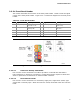
Table 21. LPC Debug Header
Pin Signal Name Pin Signal Name
1 CK_33M_DEBUG 2 GND
3 PLTRST# 4 LFRAME#
5
LAD0
6
LAD1
7 LAD2 8 LAD3
9 GND 10 GND
11 +3.3 V 12 +3.3 V
13
Key (no pin)
14
+3.3 V
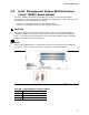
2.2.2.2 Add-in Card Connectors
The board has the following add-in card connectors:
• One PCI Express x16 (3.0/2.x/1.x)
• One PCI Express x1 (2.x/1.x)
• Two Conventional PCI (rev 2.3)
Note the following considerations for the Conventional PCI bus connectors:
• The Conventional PCI bus connectors are bus master capable.
• SMBus signals are routed to the Conventional PCI bus connectors. This enables
Conventional PCI bus add-in boards with SMBus support to access sensor data on
the desktop board. The specific SMBus signals are as follows:
The SMBus clock line is connected to pin A40.
The SMBus data line is connected to pin A41.