Intel Express 100BASE-T4 Stackable Hub User Guide 656943-002
First edition August 1996 Second edition December 1996 Copyright © 1996, Intel Corporation. All rights reserved. Intel Corporation, 5200 NE Elam Young Parkway, Hillsboro OR 97124-6497 Intel Corporation assumes no responsibility for errors or omissions in this manual. Nor does Intel make any commitment to update the information contained herein. * Other product and corporate names may be trademarks of other companies and are used only for explanation and to the owners’ benefit, without intent to infringe.
Contents Quick Start Chapter 1 1 Overview 3 Features ............................................................................................................................................ 3 Physical Description .......................................................................................................................... 4 Chapter 2 Installing the Express Hub 9 Requirements ...............................................................................................................
C O N T E N T S Index Customer Support iv Intel Express 100BASE-T4 Stackable Hub 37 Inside back cover
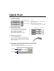
Quick Start 1 Install the hub(s). Maximum stack: Six hubs Rack requirements: Standard 19-in (48.26 cm), 1.5 EIA rack-mount space for each hub Shelf requirements: Support for 10 lbs (4.5 kg) per hub 12.3 lbs (5.6 kg) with uplink module and NMM 2 Connect the stack. Use the cascade cables to connect multiple hubs. You need to purchase cascade cables separately from your network services supplier (see Appendix B for more information). Do not use UTP cabling to connect hubs. 3 Connect the devices.
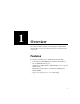
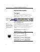
1 Overview This chapter includes a summary of the Intel Express 100BASE-T4 Stackable Hub’s features and a physical description of the hub and its components. Features Key features of the Intel Express 100BASE-T4 Stackable Hub • Compatibility with the IEEE 802.3u standard for Fast Ethernet. • Twelve 100BASE-T4 fixed ports. • Uplink path to 100BASE-TX or 100BASE-FX devices via optional uplink modules. • Hub management through the optional Network Management Module (NMM).
C H A P T E R 1 Intel Express 100BASE-T4 Stackable Hub Physical Description Front panel The front panel of the Express Stackable Hub provides twelve 100BASE-T4 ports, an LED matrix (see “LED matrix” later in this chapter for a description of LEDs), a media adapter slot, and an expansion slot.
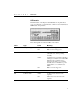
C H A P T E R 1 Overview LED matrix The LED matrix on the Express Stackable Hub’s front panel allows you to view the hub’s operational status, collisions, network utilization, NMM status, and port status. The following table describes the LEDs on the matrix. Label Type Pwr Hub power supply status Green Stat Hub status Color Meaning Hub is receiving power. Off Hub is not receiving power. Green Hub has power, has passed the confidence test, and is operating normally.
C H A P T E R 1 Intel Express 100BASE-T4 Stackable Hub Label Type Color Meaning Data % Network utilization Green Dynamically indicates the percentage of network utilization for the Ethernet segment in a hub or a stack of hubs. Operates as a bar graph. For example, if the ≤1% and 5% Data LEDs are green, that stack’s segment is using roughly 5% of the network.
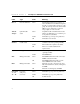
C H A P T E R 1 Overview Rear panel The rear panel of the Express Stackable Hub provides an AC power receptacle, a redundant power connector (not supported), and two cascade cable connectors. Power receptacle The AC power receptacle is provided for connecting to an AC power outlet. The Express Stackable Hub accepts between 100 and 240V AC. Cascade connectors NOTE A stack of Express Stackable Hubs can contain a maximum of six hubs.
C H A P T E R 1 Intel Express 100BASE-T4 Stackable Hub Optional equipment The Intel 100BASE-T4 Stackable Hub ships with filler panels installed in the media adapter and expansion slots. Both panels can be removed to accommodate optional modules. Media adapter slot NOTE Port 1 is disabled when the media adapter slot is filled.
2 Installing the Express Hub Requirements Rack installation requirements Standard 19-in. (48.26 cm.) EIA equipment rack 1.5 EIA rack-mount spaces available for each hub Table and shelf installation requirements Approximately 13.25-in. (33.66 cm.) by 19.25-in. (48.90 cm.) area on a level tabletop or shelf Support for at least 10 lbs. (4.5 kg.) per hub with filler panels installed in expansion and media adapter slots Support for at least 12.3 lbs. (5.6 kg.
C H A P T E R 2 Intel Express 100BASE-T4 Stackable Hub Installing a Single Hub NOTE To install the hub in a rack Only qualified technicians should install and maintain this equipment. 1 Attach the mounting brackets to the sides of the hub. 2 Align the mounting holes in the brackets with the holes in the rack. 3 Insert two pan-head screws with nylon washers through each mounting bracket and into the rack. 4 Connect the AC power cord to the hub and then to the wall outlet or power strip.
C H A P T E R 2 Installing the Express Hub Stacking Hubs NOTE If you include Intel Express 100BASE-TX and 100BASE-T4 Stackable Hubs in the same stack, make sure you attach only the appropriate devices (TX or T4) to each type of hub. You can install a maximum of six hubs in an equipment rack or on a shelf or a table. Once the hubs are stacked and secured, connect them using Intel cascade cables. The cascade cable is a unique cable for Express Stackable Hubs.
C H A P T E R 2 Intel Express 100BASE-T4 Stackable Hub Removing a Hub from a Stack To remove the hub from a rack CAUTION When you remove a hub from the middle of the stack (any hub located between two operating hubs) and don’t reattach the cascade cables, you split the Ethernet segment into two separate segments. CAUTION Check that the screw locks on the cable connectors are fully tightened and the cable connection is secure. A faulty cable connection could disrupt the operation of the entire stack.
C H A P T E R 2 Installing the Express Hub Adding a Network Management Module (NMM) After powering down the hub, install the NMM in the hub at the top of your stack. When an NMM is installed in the stack, it automatically numbers the hubs in the stack. After you install the NMM and reconnect the power cord, the entire stack of hubs resets, and you temporarily lose port connectivity to each hub. For more information on installing the NMM, see the Express Stackable Hub Network Management Module User Guide.
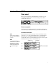
3 Connecting the Devices Connecting Cables to the Hub NOTE Make sure your network conforms to the Fast Ethernet rules described in Appendix A. Connect devices directly to ports on the Express 100BASE-T4 Stackable Hub or to ports on installed uplink modules. This illustration shows how to connect a UTP cable to an RJ-45 connector and a fiber optic cable to an SC connector. NOTE 100BASE-T4 devices use 4-pair Category 3, 4, or 5 UTP cabling. 100BASE-TX devices use 2-pair Category 5 UTP cabling.
C H A P T E R 3 Intel Express 100BASE-T4 Stackable Hub You can connect the following 100 Mbps devices to the ports on the Express Stackable Hub and optional uplink modules: • Workstations • Servers • Printers • Transceivers • Switching hubs • Routers • Printers • Print servers See “Using a switch to connect hubs” later in this chapter for information about connecting to 100 Mbps switching hubs.
C H A P T E R 3 Connecting the Devices • The Data % LEDs light green on each hub, indicating the overall network utilization percentage of the Ethernet segment. Because a stack of hubs is a single segment, utilization is the same for each hub in the stack. • If an optional uplink module is installed in the media adapter slot, the appropriate cable is connected to the media adapter port, and the link status is good, the Media Adapter LED lights green. When this LED is on, port 1 on the hub is disabled.
C H A P T E R 3 Intel Express 100BASE-T4 Stackable Hub Unit Numbering Convention NOTE A stack of Express Stackable Hubs can contain a maximum of six hubs. When Express Hubs are stacked, cascaded, and powered, they are assigned “unit” numbers that are stored in the hub’s nonvolatile memory. Hub numbers are assigned according to a hub’s physical location in the stack. The NMM assigns numbers from the top down— the hub at the top of the stack is numbered 1, the hub below hub 1 is numbered 2, and so on.
C H A P T E R 3 Connecting the Devices Using a Switch to Connect Hubs Integrating switching into the network enables network segmentation, which increases the total capacity and performance. You can add 100 Mbps workgroups to the network and connect them to individual ports on a Fast Ethernet switch. The illustration below shows how Express Stackable Hubs interface with a switching hub to increase the total capacity and performance of an entire network.
C H A P T E R 3 Intel Express 100BASE-T4 Stackable Hub Connecting to Non100BASE-T4 devices Connecting to 100BASE-TX devices You have two options for connecting the Express 100BASE-T4 Stackable Hub to a 100BASE-TX device: • an Intel 100BASE-TX Uplink Module • a routing server equipped with a 100BASE-T4 NIC and a 100BASE-TX NIC You can also use Intel cascade cables to combine Express 100BASE-TX Stackable Hubs with Express 100BASE-T4 Stackable hubs in a stack.
C H A P T E R 3 Connecting the Devices Routing server If you’re using a NOS that supports multi-protocol routing, such as Novell NetWare* or Windows NT*, an inexpensive way to connect the 100BASE-T4 and 100BASE-TX segments is to install both a 100BASE-T4 and 100BASE-TX LAN adapter in your server and let the server bridge the segments. Connecting to 100BASE-FX devices NOTE Port 1 on a hub is disabled when an uplink module is installed.
C H A P T E R 3 Intel Express 100BASE-T4 Stackable Hub 100BASE-TX Uplink Module and 10/100 Downlink NOTE Port 1 on a hub is disabled when an uplink module is installed. Intel’s 100BASE-TX Uplink Module fits in the hub’s media adapter slot and allows you to connect to 100BASE-TX devices, such as the Express 10/100 Downlink. The Express 10/100 Downlink allows you to connect to 10BASE-T devices.
A Fast Ethernet Topology Rules This appendix describes • 100BASE-T physical layer media specifications • repeater rules For a complete explanation of the set of 100BASE-T rules and guidelines, refer to the Institute of Electrical and Electronics Engineers (IEEE) 100BASE-T 802.3u standard. For information about cables for Ethernet networks, refer to the Electronic Industries Association/Telecommunications Industry Association (EIA/TIA) wiring standard EIA/TIA 568.
A P P E N D I X A Intel Express 100BASE-T4 Stackable Hub Media specification Cable type(s) Connector type(s) Coding scheme 100BASE-T4 CAT 3, 4, 5 UTP (4-pair wire) RJ-45 8B/6T 100BASE-TX CAT 5 UTP (2-pair wire) RJ-45 4B/5B 100BASE-FX 62.5/125 micron SC fiber optic cable (2 multi-mode fibers) 4B/5B Basic Rules When deploying 100BASE-T4 Fast Ethernet, you should follow three basic rules: • UTP cable length from repeater to workstation or switch can’t exceed 100 meters (328 feet).
A P P E N D I X A Fast Ethernet Topology Rules Repeater rules The 100BASE-T standard defines two types of repeaters — Class I and Class II. The Express Stackable Hub is a Class I repeater. Class I repeaters (sometimes called translational repeaters) limit the number of repeaters in a physical domain to one. However, the one-repeater maximum for Class I repeaters does not limit the port density of 100BASE-T networks when stackable hubs are used.
A P P E N D I X A Intel Express 100BASE-T4 Stackable Hub Network Topology Extensions You can extend the network topology by connecting Express Stackable Hubs to a switching hub. In the illustration below, the network topology is extended to a maximum of 400 meters (1312 feet). In this network, a switching hub interconnects two separate repeater stacks to form two separate collision domains.
A P P E N D I X A Fast Ethernet Topology Rules In the next illustration, the network topology is extended to a maximum distance of 491 meters (1610 feet). In this network, a 160 meter (524 feet) fiber link connects the 100BASE-TX repeater to the switch, and a 131 meter (429 feet) fiber link connects the 100BASET4 repeater to the switch. 100 meter (328 feet) Category 5 UTP wiring connects workstations and servers to the repeater stacks.
A P P E N D I X A Intel Express 100BASE-T4 Stackable Hub You can extend the 100BASE-T network topology further by interconnecting the switches using fiber links. Interconnecting two switches creates a network that contains four separate collision domains. The overall network topology grows while each collision domain can be modeled after the extended collision domains shown in the previous two illustrations.
B Optional Equipment and Technical Specifications This appendix describes optional equipment supported by the Express 100BASE-T4 Stackable Hub and provides technical specifications for the hub. Optional Equipment Uplink modules The 100BASE-TX and 100BASE-FX uplink modules fit into the media adapter slot and provide a connection to other 100 Mbps equipment in your network. The Intel 100BASE-TX Uplink Module (Intel product code EC100MATX) provides a standard RJ-45 connector for Category 5 UTP cable.
A P P E N D I X B Intel Express 100BASE-T4 Stackable Hub Network Management Module (NMM) The Intel Express Stackable Hub Network Management Module (Intel product code EC100NMM) fits into the expansion slot and allows you to extend per-port advanced Simple Network Management Protocol (SNMP) management functions to each Express Stackable Hub in the stack. Advanced SNMP management allows you to communicate with SNMP-compatible software to • monitor network statistics and view errors and hardware status.
A P P E N D I X B Optional Equipment and Technical Specifications Technical Specifications Network Protocol and Standards Compatibility IEEE 802.3u 100BASE-T Data Rate T4: 100 Mbps with 8B/6T coding scheme TX: 100 Mbps with 4B/5B coding scheme FX: 100 Mbps with 4B/5B coding scheme Electrical Specifications Input power: Thermal rating: AC line frequency: Input voltage (rms): Volt amperes rating: 160 W 550 BTU/hr 47–63 Hz 90–264 V AC 250 VA Physical Specifications Dimensions: 11.18 (l) by 17.25 (w) by 2.
A P P E N D I X B Intel Express 100BASE-T4 Stackable Hub Safety Agency Approvals UL listed (UL 1950) Third Edition UL listed for Canada TUV certified to IEC 950 Second Edition plus A1/A2 and EN60950 A1/A2 Repeater Type I Class I repeater Interface Options RJ-45 connectors for 4-pair Category 3, 4, or 5 UTP 100BASE-T4 Ethernet interface RJ-45 connectors for 2-pair Category 5 UTP 100BASE-TX Ethernet interface with installed 100BASE-TX uplink module Fiber optic SC connectors for 100BASE-FX Ethernet interf
A P P E N D I X B Optional Equipment and Technical Specifications Statement of Conditions In the interest of improving internal design, operational function, or reliability, Intel Corp. reserves the right to make changes to the products described in this document without notice. Intel Corp. does not assume any liability that may occur due to the use or application of the products or circuit layouts described herein.
A P P E N D I X B Intel Express 100BASE-T4 Stackable Hub WARNING The system is designed to operate in a typical office environment. Choose a site that is: · Clean and free of airborne particles (other than normal room dust). · Well ventilated and away from sources of heat including direct sunlight. · Away from sources of vibration or physical shock. · Isolated from strong electromagnetic fields produced by electrical devices.
A P P E N D I X B Optional Equipment and Technical Specifications AVVERTENZA Il sistema è progettato per funzionare in un ambiente di lavoro tipico. Scegliere una postazione che sia: · · · · · · Pulita e libera da particelle in sospensione (a parte la normale polvere presente nell’ambiente). Ben ventilata e lontana da fonti di calore, compresa la luce solare diretta. Al riparo da urti e lontana da fonti divibrazione. Isolata dai forti campi magnetici prodotti da dispositivi elettrici.
A P P E N D I X B Intel Express 100BASE-T4 Stackable Hub Limited Warranty Intel warrants to the original owner that the product delivered in this package will be free from defects in material and workmanship for three (3) years following the latter of: (i) the date of purchase only if you register by returning the registration card as indicated thereon with proof of purchase; or (ii) the date of manufacture; or (iii) the registration date if by electronic means provided such registration occurs within 30
I Index 1 Media Adapter LED operating conditions 6 verifying installation 17 100BASE-FX data rate 31 devices, connecting to 21 distance limitations 24, 27 media specification 24 uplink module 29 100BASE-FX Uplink Module installation guidelines 12 using 21 100BASE-T network topology extensions 26 switched LAN 19 100BASE-T4 data rate 31 distance limitations 24, 26 media specification 24 100BASE-T4 ports connecting cables 15 100BASE-TX data rate 31 devices, connecting to 20 media specification 24 uplink modu
I N D E X Intel Express 100BASE-T4 Stackable Hub Coding schemes media specifications 24 Col LED operating conditions 5 Confidence test 16 Connecting cables 15 to 100BASE-FX devices 21 to 100BASE-TX devices 20 to 10BASE-T devices 21 to non-100BASE-T4 devices 20 Connecting hubs using a switch 19 using cascade cables 11 D–F Data % (utilization) LED operating conditions 6 verifying installation 17 Data rate 100BASE-FX 31 100BASE-T4 31 100BASE-TX 31 Dimensions, physical 31 Distance limitations collision d
I N D E X Intel Express 100BASE-T4 Stackable Hub matrix 4 Mstr 6 Port Status 6, 17 Pwr 5, 16 Stat 5, 16 Length cables 24 collision domain 24 M–O Management module description 30 installing 13 numbering convention 11 Management Mstr LED operating conditions 6 verifying installation 17 Management Stat LED operating conditions 6 verifying installation 17 Media Adapter LED operating conditions 6 verifying installation 17 Media adapter slot 8 Media specification coding schemes 24 Mounting brackets install
I N D E X Intel Express 100BASE-T4 Stackable Hub Restrictions, power cords 10 RJ-45 connectors connecting cable 15 hub front panel 4 interface options 32 media specification parameters 24 pin pairings 4 pinouts 4 Rules cable length 24 distance limitations 24 repeater 25 Safety agency approvals 32 SC connectors 15, 24, 32 Service access 9 SNMP 30 Specifications physical layer media 23 Stacking 100BASE-T4 and 100BASE-TX hubs 100BASE-T4 hubs 11 100BASE-TX and 100BASE-T4 hubs numbering convention 18 Stand
Intel Automated Customer Support You can reach Intel’s automated support services 24 hours a day, every day at no charge. The services contain the most up-to-date information about Intel products. You can access installation instructions, troubleshooting information, and general product information. World Wide Web & Internet FTP Access Intel’s World Wide Web home page or download information using anonymous FTP.