
Datasheet

Pulse Width Modulators
August 2016 Intel® Joule™ Datasheet
Document number: 566641 rev. 1.0 Page 28
13 Pulse Width Modulators
The default BIOS configuration table defines four dedicated PWM outputs as PWM_0, PWM_1, PWM_2, and PWM_3, each
with programmable frequency and duty cycle.
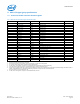
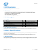
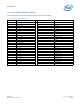
Table 16 shows examples of hardware (register) based PWM programming:
The PWM variables that control frequency and duty cycle are controlled by the BASE_UNIT_INT, BASE_UNIT_FRAC, and
ON_TIME_DIVISOR register settings and the following equations:
Note: Consult specific operating system documents if manipulating PWM settings at the OS level.
14 Universal Serial Bus
14.1 Available USB ports
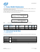
The Intel® Joule™ module provides two USB 3.0 ports; one Type C (OTG) and one USB 3.0 host mode and a USB 2 host port.
Refer to the Intel® Joule™ Expansion Board Design Guide for the specifications and PCB routing guidance for this interface.
Table 16 PWM programming examples
Integer part of
BASE_UNIT_INT
(bits 29:22)
Fractional part of
BASE_UNIT_FRAC
(bits 21:8)
Decimal
base unit
value
ON_TIME_DIVISOR
(bits 7:0)
Base unit
type
PWM
frequency
(Hz)
PWM
period
(uSec)
Duty
Cycle
0000_0000b 00_0100_0000_0000b 0.0625 0000_1000b fractional 4,688 213 50%
0000_0000b 00_0010_0000_0000b 0.03125 0000_0100b fractional 2,344 427 50%
0000_0000b 00_0001_0000_0000b 0.015625 0000_0001b fractional 1,172 853 50%
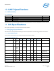
Table 17 USB port types
Signal name Port Description
USB2_0_DP 0 USB 2 data positive
USB2_0_DN USB 2 data negative
USB3_1_RX_DP 1 USB 3 receive data positive
USB3_1_RX_DN USB 3 receive data negative
USB3_1_TX_DP USB 3 transmit data positive
USB3_1_TX_DN USB 3 transmit data negative