
User's Manual
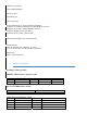
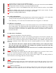
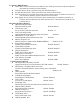


IDE1/IDE2 Primary/ Secondary IDE port
SATA1/SATA2 SATA Port
FDD Floppy Disk Drive Connector port
PW1/PW2 ATX Power Supply Connector Port
CPU FAN/2
n
d
FAN CPU/ System FAN port
WOL Wake-on-Lan Connector port
IRDA Irda Infrared port
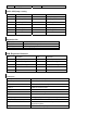
Function port panel
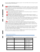
Power Supply LED Pin 1: Power Supply Anode; Pin3: Ground
HDD LED Pin2: power supply Anode; Pin: LED Signal
Power Supply Switch Pin8 10: Switch Signal
Reset Switch Pin4 16: Reset Switch
Speaker Output Pin9: Speaker Output; Pin15: Power Supply Anode
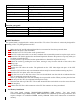
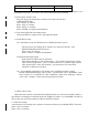
4.2 CPU Installation
The system board is equipped with a surface mount LGA 775 socket. This socket is exclusively designed for
installing a LGA 775 packaged Prescott CPU
1. Make sure the PC and all other peripheral devices connected to it has been powered down.
2. Disconnect all power cords and cables.
3. Locate the LGA 775 CPU socket on the system board
4. The CPU socket cones with a cover that is attached with a removable protective cap the cap is used to
protect the CPU Socket against dust and harmful particles. Remove the protective cap only when you
are about to install the CPU.
5. Lift the protective cap from the location pointed below to detach the cap from the cover.
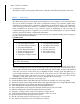
6. Unlock the socket by pushing the lever down, moving it away from the side tab of the socket, then
lifting it up.
7. Now lift the cover.
8. Position the CPU above the socket. The gold mark on the CPU. Must slign with pin 1 of the CPU
socket,
9. Insert the CPU will fit in only one orientation and can easily be inserted without exerting any force.
10. Once the CPU is in place, move the cover down.
11. Push the lever sown to lock the socket. The lever should hook onto the side tab to indicate that the
CPU is completely secured in the socket.
12. Before you install the fan/ hest sink assembly do not spread the surface. When you later place the heat
sink on top of the CPU, the compound will disperse evenly.
13. Place the heat sink top of the CPU. The 4 studs around the heat sink which are used to secure the heat
sink into place.
14. Connect the CPU fan’s cable connector to the CPU fan connector on the system board.
4.3 Memory installation
This main board supports DDR266/DDR333/DDR400 DDR memory. You may install
128/256/512MB 184 pin DDR memory. DDR SDRAM uses additional power and ground lines and
requires 184-pin 2.5V unbuffered DIMM used by SDRAM. Follow these instructions to install the
memory: