
User's Manual
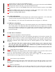


1. Push the latches on each side of the DIMM slot down.
2. Align the memory module with the slot. The DIMM slots are keyed with notches and the DIMMs
are keyed with cutouts so that they. Can only be installed correctly.
3. Check that the cutouts on the DDIMM module edge connector match the notches in the DIMM
slot.
4. Install the DIMM module into the slot and press it firmly down Until it seats correctly. The slot
latches levered upwards and latch on to the edges of the DIMM.
5. Install any remaining DIMM modules.
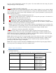
4.4 AGP Card Installation
This main board has an Accelerated Graphics port (AGP) slot that support 8X (+1.5V) cards when
you buy an AGP card, make sure that you ask for on with +1.5V specification.
Note: Install only +1.5V AGP card, This mother board does not support 3.3V AGP cards
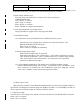
4.5 IDE Devices Installation
IDE devices include hard high drives, high- density diskette drives, and CD-ROM or DVD-ROM
drives among others. The main board ships with and IDE cable that can support one or two IDE
devices if you connect two IDE devices to a single cable, you must the device as a Master and one
of the drives as Slave. To the device as a Master or Slave Device. The Master device connects to
the end of the cable.
4.6 Other Device Installation
4.6.1 Serial ATA Installation (7-Pin SATA/SATA2)
The motherboard bundles the new Serial ATA technology through the SATA interfaces onboard. The
SATA specification allows for thinner, more flexible cables with lower pin count, reduced voltage
requirement. These connectors support serial ATA HDDs and allow up to 150MB/ s data transfer rate
using thin 4-conductor SATA cables faster than the standard parallel ATA with 133MB/s (Ultra
ATA/133)
Note: The Serial ATA cable is smaller and more flexible allowing easier routing the chassis
the lower pin count of the serial ATA cable eliminates the problem caused by the wide, flat
ribbon cables of the parallel ATA interface.
Hot plug support for Serial ATA drive and connections are not available in this motherboard.
4.6.2 Floppy Disk Drive Installation
The main board ships with a floppy disk drive cable that can support one or two drives. Drives can be
3.5”or 5.25” wide with capacities of 360K, 720K, 1.2MB, 1.44MB, or 2.88MB.
Install your drives and connect power from the system power supply. Use the cable provided to
connect the drives to the floppy disk drive connector floppy
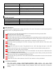
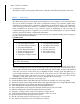
4.6.3 Sound connector port installation
This main board has three audio ports connect audio device the left side jack (green) is for a stereo
line-out signal. The middle jack (gray) is for a stereo line-in signal. The right side jack (red) is for a
microphone.
4.6.4
Wake on LAN(WOL)
If you have installed a LAN card, use the cable provided with the card to plug into the main board
WOL connector. This enable the wake on Lan feature when you system is in a power saving mode,