
User's Manual


any Lan signal automatically resumes the system. You must enable this item using the power
management page of the setup utility.
4.6.5 Clear CMOS (Clear RTC RAM) (Jp6)
This jumper allows you to clear the Real Time clock (RTC) RAM in CMOS. You can clear the CMOS
memory of data, time, and system setup parameters by crasing the CMOS RTC RAM data. The RAM
data in CMOS that include system setup information such as system passwords is powered by the
onboard button cell battery.
1. Turn OFF the computer and unplug the power cord.
2. Move the jumper cap from Pin 1-2 (default) to pin 2-3 keep the cap on pin 2-3 for about 5-10
seconds, then move the cap back to pins 1-2.
3. Plug the power cord and turn on the computer
4. Hold down the <DEL> key during the boot process and enter BIOS setup to re-enter data.
Note 1: Except when clearing RTC RAM, never remove the cap on CLRTC1 jumper default
position removing the cap will cause system boot failure!
Note 2: you do not need to clear to clear the RTC when the system hangs due to over clocking. For
system failure due to overclocking, use the C.P.R (CPU Parameter Recall) feature shut down and
reboots the system so BIOS can automatically reset parameter settings to default values.
4.6.6 ATX power connectors (20-pin PW1, 4-Pin PW2)
These connectors connect to an ATX 12V power supply. The plugs from the power supply are
designed to fit these connectors in only one orientation. Find the proper orientation and push down
firmly until the connectors completely fit. In addition to the 20-pin PW1 connector, connect the 4-pin
ATX +12V power plug to provide sufficient power to the CPU.
Note1: Make sure that your ATX 12V power supply can provide at least 15A on the +12V lead and at
least 2A on the +5V standby lead (+5VSB). The minimum recommended wattage is 300W or above
for a fully configured system. The system may become unstable and may experience difficulty
powering up if the power supply is inadequate.
Note2: Do not forget to connect the 20-Pin ATXPWR1 and 4-pin ATX12V1 power plugs. Failure to
do so may cause severe damage to the CPU or mother board!
Chapter 5 Driver Installation
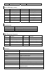
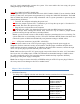
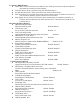
1.1 Installation Directory
The utility CD is supplied with that main board the connects contained in it are showed as below:
Directory Driver OS
INTEL\INF\ Intel chipset software Windows 9X
Windows 2000/XP
Windows NT4.0
SOUND\REALTEK\ Realtek AC’97 Audio driver Windows 9X
Windows 2000/XP
Windows NT4.0
INTEL\usb2.0\865\ VGADRIVER SETUP Windows 9X
Windows 2000/XP
Windows NT4.0
INTEL\VGA\865\ VGA driver setup Windows 9X
Windows 2000/XP