
User's Manual

Intel Desktop Board D810EMO/MO810E Technical Product Specification
12
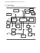
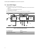
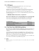
1.1.3 Block Diagram
Figure 2 is a block diagram of the major functional areas of the board.
Port 3
810E Chipset
PPGA370
Processor
Socket
DIMM
Socket
Primary/
Secondary IDE
Interface
LPC I/O
Controller
Serial Port
ATA33/66
Port 0USB
PCI Bus
Connector
66/100/133
MHz Host Bus
PCI Bus
Analog
Codec
LAN
Subsystem
PCI Bus
Hardware
Monitor
10/100
Mbps
Ethernet
82801AA I/O Controller Hub
(ICH)
82810E
Graphics Memory
Controller Hub
(GMCH)
82802AB
Firmware Hub
(FWH)
100 MHz
SDRAM
Bus
AHA
Bus
Display
Interface
VGA
Port
4 MB
Display
Cache
OM09093
Line Out
Mic In
CD-ROM
Port 2
USB
Hub
LPC
Bus
Port 1
SMBus
Digital
Controller
AC ’97 Link
PCI Bus
Figure 2. Block Diagram