
Desktop Board DH57JG Manual


Installing and Replacing Desktop Board Components
45
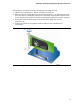
Front Panel Audio Header
The front panel audio header shown in Figure 20, A supports both Intel High Definition
(HD) Audio and AC ’97 Audio.
Table 7 shows the pin assignments and signal names for
HD Audio and Table 8 shows
the pin assignments and signal names for AC ’97 Audio.
Table 7. Front Panel Audio Signal Names for Intel HD Audio
Pin Signal Name Pin Signal Name
1 PORT 1L (Microphone) 2 GND
3 PORT 1R (Microphone) 4 PRESENCE#
5 PORT 2R (Headphone) 6 SENSE1_RETURN
7 SENSE_SEND 8 KEY (no pin)
9 PORT 2L (Headphone) 10 SENSE2_RETURN
Table 8. Front Panel Audio Header Signal Names for AC ’97 Audio
Pin Signal Name Pin Signal Name
1 MIC 2 AUD_GND
3 MIC_BIAS 4 PRESENCE#
5 FP_OUT_R 6 AUD_GND
7 No connect 8 KEY (no pin)
9 FP_OUT_L 10 AUD_GND
Alternate Front Panel Power LED Header
Figure 20, B shows the location of the alternate front panel power LED header. Pins 1
and 3 of this header duplicate the signals on pins 2 and 4 of the front panel header. If
your chassis has a three-pin power LED cable, connect it to this header. Table 9
shows
the p
in assignments for the alternate front panel header.
Table 9. Alternate Front Panel Power LED Header Signal Names
Pin Signal Name In/Out
1 Front panel LED+ Out
2 No pin
3 Front panel LED- Out