
User's Manual


6-13
STANDARD AND PTS INTERRUPTS
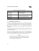
6.5.2 Modifying Interrupt Priorities
Your software can modify the default priorities of maskable interrupts by controlling the interrupt
mask registers (INT_MASK and INT_MASK1). For example, you can specify which interrupts,
if any, can interrupt an interrupt service routine. The following code shows one way to prevent
all interrupts, except EXTINT3 (priority 14), from interrupting an SIO receive interrupt service
routine (priority 06).
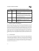
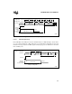
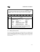
INT_MASK1
Address:
Reset State:
0013H
00H
The interrupt mask 1 (INT_MASK1) register enables or disables (masks) individual interrupt requests.
(The EI and DI instructions enable and disable servicing of all maskable interrupts.) INT_MASK1 can
be read from or written to as a byte register. PUSHA saves this register on the stack and POPA
restores it.
7 0
NMI EXTINT3 EXTINT2 OVR2_3 OVR0_1 EPA3 EPA2 EPA1
Bit
Number
Function
7:0 Setting a bit enables the corresponding interrupt.
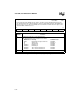
The standard interrupt vector locations are as follows:
Bit Mnemonic Interrupt Standard Vector
NMI Nonmaskable Interrupt FF203EH
EXTINT3 EXTINT3 pin FF203CH
EXTINT2 EXTINT2 pin FF203AH
OVR2_3
†
EPA Capture Channel 2 or 3 Overrun FF2038H
OVR0_1
†
EPA Capture Channel 0 or 1 Overrun FF2036H
EPA3 EPA Capture/Compare Channel 3 FF2034H
EPA2 EPA Capture/Compare Channel 2 FF2032H
EPA1 EPA Capture/Compare Channel 1 FF2030H
†
An overrun on the EPA capture/compare channels can generate the multiplexed
capture overrun interrupts. The EPA_MASK and EPA_PEND registers decode these
multiplexed interrupts. Write to EPA_MASK to enable the interrupt sources; read
EPA_PEND to determine which source caused the interrupt.
Figure 6-6. Interrupt Mask 1 (INT_MASK1) Register