
User's Manual

6-17
STANDARD AND PTS INTERRUPTS
6.6 INITIALIZING THE PTS CONTROL BLOCKS
Each PTS interrupt requires a block of data, in register RAM, called the PTS control block
(PTSCB). The PTSCB identifies which PTS microcode routine will be invoked and sets up the
specific parameters for the routine. You must set up the PTSCB for each interrupt source before
enabling the corresponding PTS interrupts.
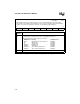
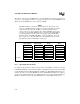
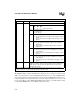
INT_PEND1
Address:
Reset State:
0012H
00H
When hardware detects a pending interrupt, it sets the corresponding bit in the interrupt pending
(INT_PEND or INT_PEND1) registers. When the vector is taken, the hardware clears the pending bit.
Software can generate an interrupt by setting the corresponding interrupt pending bit.
7 0
NMI EXTINT3 EXTINT2 OVR2_3 OVR0_1 EPA3 EPA2 EPA1
Bit
Number
Function
7:0 Any set bit indicates that the corresponding interrupt is pending. The interrupt bit is
cleared when processing transfers to the corresponding interrupt vector.
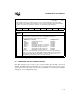
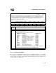
The standard interrupt vector locations are as follows:
Bit Mnemonic Interrupt Standard Vector
NMI Nonmaskable Interrupt FF203EH
EXTINT3 EXTINT3 pin FF203CH
EXTINT2 EXTINT2 pin FF203AH
OVR2_3
†
EPA Capture Channel 2 or 3 Overrun FF2038H
OVR0_1
†
EPA Capture Channel 0 or 1 Overrun FF2036H
EPA3 EPA Capture/Compare Channel 3 FF2034H
EPA2 EPA Capture/Compare Channel 2 FF2032H
EPA1 EPA Capture/Compare Channel 1 FF2030H
†
An overrun on the EPA capture/compare channels can generate the multiplexed
capture overrun interrupts. The EPA_MASK and EPA_PEND registers decode these
multiplexed interrupts. Write to EPA_MASK to enable the interrupt sources; read
EPA_PEND to determine which source caused the interrupt.
Figure 6-8. Interrupt Pending 1 (INT_PEND1) Register