
User's Manual

6-29
STANDARD AND PTS INTERRUPTS
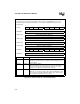
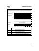
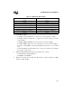
PTS PWM Toggle Mode Control Block
In PWM toggle mode, the PTS uses a single EPA channel to generate a pulse-width modulated (PWM)
output signal. The control block contains registers that contain the PWM on-time (PTSCONST1), the
PWM off-time (PTSCONST2), the address pointer (PTSPTR1), and a control register (PTSCON).
7 0
PTSCONST2 (H)
PWM Off-time (high byte)
7 0
PTSCONST2 (L)
PWM Off-time (low byte)
15 8
PTSCONST1 (H)
PWM On-time (high byte)
7 0
PTSCONST1 (L)
PWM On-time (low byte)
15 8
PTSPTR1 (H)
Pointer 1 Value (high byte)
7 0
PTSPTR1 (L)
Pointer 1 Value (low byte)
7 0
PTSCON
M2 M1 M0 — — — TMOD TBIT
7 0
Unused
0 0 0 0 0 0 0 0
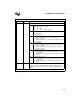
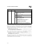
Register Location Function
PTSCONST2 PTSCB + 6 PWM Off-time
Write the desired PWM off-time to these bits.
PTSCONST1 PTSCB + 4 PWM On-time
Write the desired PWM on-time to these bits.
PTSPTR1 PTSCB + 2 Pointer 1 Value
These bits point to a memory location, usually EPA
x
_TIME. PTSPTR1
can point to any unreserved memory location within page 00H.
Figure 6-15. PTS Control Block — PWM Toggle Mode