
User's Manual


Intel
®
IXP42X product line and IXC1100 control plane processors—Expansion Bus Controller
Intel
®
IXP42X Product Line of Network Processors and IXC1100 Control Plane Processor
DM September 2006
292 Order Number: 252480-006US
8.0 Expansion Bus Controller
The Expansion Bus Controller provides an interface from internal South AHB to external
flash, Host-Port Interfaces (HPI), SRAM and other devices such as ATM control
interfaces, and DSPs used for voice applications.
The Expansion Bus includes a 24-bit address bus and a 16-bit-wide data path and maps
transfers between the South AHB and external devices. Intel and Motorola*,
multiplexed and non-multiplexed, micro-controller-style address/data bus accesses are
both supported using the expansion interface. Applications having less than 16-bit
external data paths may connect to an 8-bit interface.
The Expansion Bus Controller occupies 256 Mbytes of address space in the Intel
®
IXP42X Product Line of Network Processors and IXC1100 Control Plane Processor’
memory map. Eight chip selects are supported to allow up to eight independent
external devices to be connected. The address space for each chip select is up to
16 Mbytes.
A clock input is required to operate the expansion interface. The maximum clock
frequency supported by the Expansion Bus Controller is 66.66 MHz. The clock input is
provided to allow a wide variety of different peripherals to be connected to the
expansion interface.
GPIO 15 provides a clock output after reset. The clock produced by GPIO 15 is
programmable at speeds up to 33.33 MHz and can be used to provide the clock input to
the expansion bus interface. GPIO 15 must be externally routed on the board to
connect to EX_CLK.
This implementation gives the designer the option to choose between a lower part
count and the speed of the interface operations.
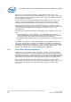
To provide a glueless interface to a wide variety of devices, the Expansion Bus
Controller supplies eight chips selects to a 16-bit-wide external bus, which can be
configured as Intel, Motorola, or HPI-style controls. The signaling characteristics and
timing for each chip select is individually programmable. After chip reset, chip-select 0
defaults to conservative timing values for controlling a flash device and the size of the
flash is determined by the value of Expansion Bus Address bit 0 at the de-assertion of
RESET_IN_N signal. The Expansion Bus address bit all have internal pull-up resistors.
Each bit may be pulled low by placing a pull-down resistor on the address signal. The
remaining chip selects are un-programmed.
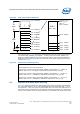
The Expansion Bus Controller contains configuration registers beyond what is required
for its own configuration. There are several bits of configuration signals provided as
output from the Expansion Bus Controller to the rest of the Intel
®
IXP42X product line
and IXC1100 control plane processors. These signals provide the AHB with function like
the software interrupt capabilities, location of Expansion Bus Controller in IXP42X
product line and IXC1100 control plane processors’ memory map, PCI Host/Arbiter
information, and configuration information on devices connected to the Expansion Bus
and SDRAM Controller.