Intel® 5000 Series Chipset Memory Controller Hub(MCH) Thermal/Mechanical Design Guide May 2006 Document Number: 313067-001
INFORMATION IN THIS DOCUMENT IS PROVIDED IN CONNECTION WITH INTEL® PRODUCTS. EXCEPT AS PROVIDED IN INTEL’S TERMS AND CONDITIONS OF SALE FOR SUCH PRODUCTS, INTEL ASSUMES NO LIABILITY WHATSOEVER, AND INTEL DISCLAIMS ANY EXPRESS OR IMPLIED WARRANTY RELATING TO SALE AND/OR USE OF INTEL PRODUCTS, INCLUDING LIABILITY OR WARRANTIES RELATING TO FITNESS FOR A PARTICULAR PURPOSE, MERCHANTABILITY, OR INFRINGEMENT OF ANY PATENT, COPYRIGHT, OR OTHER INTELLECTUAL PROPERTY RIGHT.
Contents 1 Introduction .............................................................................................................. 7 1.1 Design Flow........................................................................................................ 7 1.2 Definition of Terms .............................................................................................. 8 1.3 Reference Documents ..........................................................................................
A Thermal Solution Component Suppliers....................................................................41 A.1 Tall Torsional Clip Heatsink Thermal Solution .........................................................41 A.2 Short Torsional Clip Heatsink Thermal Solution ......................................................42 B Mechanical Drawings ...............................................................................................
Tables 3-1 3-2 3-3 5-1 6-1 6-2 B-1 Intel® 5000P Chipset MCH Thermal Specifications ................................................. 13 Intel® 5000V Chipset MCH Thermal Specifications................................................. 13 Intel® 5000X Chipset MCH Thermal Specifications................................................. 14 Thermocouple Attach Support Equipment ............................................................. 17 Honeywell PCM45 F TIM Performance as a Function of Attach Pressure .....
Revision Table Revision Number Description Date -001 Initial release of the document.
Introduction 1 Introduction As the complexity of computer systems increases, so do the power dissipation requirements. Care must be taken to ensure that the additional power is properly dissipated. Typical methods to improve heat dissipation include selective use of ducting, and/or passive heatsinks. The goals of this document are to: • Outline the thermal and mechanical operating limits and specifications for the Intel® 5000 Series chipset memory controller hub (MCH).
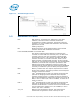
Introduction Figure 1-1. Thermal Design Process 1.2 Definition of Terms BGA Ball grid array. A package type, defined by a resin-fiber substrate, onto which a die is mounted, bonded and encapsulated in molding compound. The primary electrical interface is an array of solder balls attached to the substrate opposite the die and molding compound. BLT Bond line thickness. Final settled thickness of the thermal interface material after installation of heatsink.
Introduction 1.3 Tcase_min Minimum IHS temperature allowed. This temperature is measured at the geometric center of the top of IHS. TDP Thermal design power. Thermal solutions should be designed to dissipate this target power level. TDP is not the maximum power that the chipset can dissipate.
Introduction 10 Intel® 5000 Series Chipset Memory Controller Hub (MCH) Thermal Mechanical Design Guide
Packaging Technology 2 Packaging Technology Intel 5000 Series chipset consist of three individual components: the Memory Controller Hub (MCH), the Intel® 6700PXH 64-bit PCI Hub (PXH) and the Intel® 631xESB/632xESB I/O Controller Hub. Intel 5000 Series chipset MCH components use a 42.5 mm, 10-layer flip chip ball grid array (FC-BGA) package (see Figure 2-1, , and Figure 2-2). For information on the PXH package, refer to the Intel® 6700PXH 64-bit PCI Hub Thermal/Mechanical Design Guidelines.
Packaging Technology Figure 2-3. MCH Package Dimensions (Bottom View) AV AU AT AR AP AN AM AK AL AJ AH AG AF AE AD AC AB AA 42.5 + 0.05 - A - Y W V U T R P N M L 20.202 K J H G F E 37X 1.092 D C B A 1 2 3 4 5 6 7 8 9 10 11 12 13 14 15 16 17 18 19 20 21 22 23 24 25 26 27 28 29 30 31 32 33 34 35 36 37 38 A 37X 1.092 20.202 42.5 + 0.05 0. C 2 B A Notes: 1. All dimensions are in millimeters. 2. All dimensions and tolerances conform to ANSI Y14.5M-1994. 2.
Thermal Specifications 3 Thermal Specifications 3.1 Thermal Design Power (TDP) Analysis indicates that real applications are unlikely to cause the MCH component to consume maximum power dissipation for sustained time periods. Therefore, in order to arrive at a more realistic power level for thermal design purposes, Intel characterizes power consumption based on known platform benchmark applications. The resulting power consumption is referred to as the Thermal Design Power (TDP).
Thermal Specifications Table 3-3. Note: Intel® 5000X Chipset MCH Thermal Specifications Parameter Value Tcase_max 105°C Tcase_min 5°C TDPwith 1 active memory channel 27.3 W TDPwith 2 active memory channel 29.0 W TDPwith 4 active memory channel 32.4 W Notes These specifications are based on preliminary silicon characterization, however, they may be updated as further data becomes available.
Thermal Simulation 4 Thermal Simulation Intel provides thermal simulation models of the Intel 5000 Series chipset MCH and associated user’s guides to aid system designers in simulating, analyzing, and optimizing their thermal solutions in an integrated, system-level environment. The models are for use with the commercially available Computational Fluid Dynamics (CFD)-based thermal analysis tool FLOTHERM* (version 5.1 or higher) by Flomerics, Inc.
Thermal Simulation 16 Intel® 631xESB/632xESB I/O Controller Hub Thermal Mechanical Design Guide
Thermal Metrology 5 Thermal Metrology The system designer must make temperature measurements to accurately determine the thermal performance of the system. Intel has established guidelines for proper techniques to measure the MCH case temperatures. Section 5.1 provides guidelines on how to accurately measure the MCH case temperatures. Section 5.1.8 contains information on running an application program that will emulate anticipated maximum thermal design power (Figure 5-1). 5.
Thermal Metrology Table 5-1. Thermocouple Attach Support Equipment (Sheet 2 of 2) Item Description Part Number Calibration and Control Ice Point* Cell Omega, stable 0°C temperature source for calibration and offset TRCIII Hot Point* Cell Omega, temperature source to control and understand meter slope gain CL950-A-110 Note: 1. Three axes set consists of (1ea. U-31CF), (1ea. UX-6-6), (1ea. USM6) and (1ea. UPN-1). More information available at: http://www.narishige.co.
Thermal Metrology Figure 5-1. IHS Groove Dimensions Figure 5-2. Orientation of Thermocouple Groove Relative to Package Pin 5.1.4 Thermocouple Conditioning and Preparation 1. Use a calibrated thermocouple as specified in Table 5-1. 2. Measure the thermocouple resistance by holding both wires on one probe and the tip of thermocouple to the other probe of the DMM (compare to thermocouple resistance specifications). 3.
Thermal Metrology Figure 5-3. Bending the Tip of the Thermocouple 5.1.5 Thermocouple Attachment to the IHS Caution: To avoid the impact on the thermocouple during the SMT process, reflow must be performed before attaching the thermocouple to the grooved MCH IHS. 1. Clean the thermocouple wire groove with isopropyl alcohol (IPA) and a lint free cloth removing all residues prior to thermocouple attachment. 2. Place the thermocouple wire inside the groove letting the exposed wire and bead extend about 3.
Thermal Metrology Figure 5-4. Securing Thermocouple Wires with Kanton* Tape Prior to Attach Figure 5-5.
Thermal Metrology Figure 5-6. Position Bead on the Groove Step Figure 5-7. Using 3D Micromanipulator to Secure Bead Location Figure 5-8.
Thermal Metrology Figure 5-9. Applying the Adhesive on the Thermocouple Bead 5.1.6 Curing Process 1. Let the thermocouple attach sit in the open air for at least half an hour. Using any curing accelerator like Loctite 7452 Accelerator* for this step is not recommended. Rapid contraction of the adhesive during curing may weaken bead attach on the IHS. 2. Reconfirm electrical connectivity with DMM before removing the micromanipulator (Figure 5-8) (see Section 5.1.
Thermal Metrology 5.1.7 Thermocouple Wire Management Figure 5-10. Thermocouple Wire Management Groove Figure 5-11. Removing Excess Adhesive from the IHS Figure 5-12.
Thermal Metrology Note: Prior to installing the heatsink, be sure that the thermocouple wires remain below the IHS top surface by running a flat blade on top of the IHS for example. 5.1.8 Power Simulation Software The power simulation software is a utility designed to dissipate the thermal design power on a Intel 5000 Series chipset MCH when used in conjunction with the Dual-Core Intel® Xeon® Processor 5000 Series Processor (1333 MHz).
Thermal Metrology 26 Intel® 631xESB/632xESB I/O Controller Hub Thermal Mechanical Design Guide
Reference Thermal Solution 6 Reference Thermal Solution Intel has developed two different reference thermal solutions to meet the cooling needs of the Intel 5000 Series chipset MCH under operating environments and specifications defined in this document. This chapter describes the overall requirements for the tall torsional clip heatsink reference thermal solution including critical-to-function dimensions, operating environment, and validation criteria.
Reference Thermal Solution 6.3 Mechanical Design Envelope While each design may have unique mechanical volume and height restrictions or implementation requirements, the height, width, and depth constraints typically placed on the Intel 5000 Series chipset MCH thermal solution are shown in . When using heatsinks that extend beyond the chipset MCH reference heatsink envelope shown in Figure 6-2, any motherboard components placed between the heatsink and motherboard cannot exceed 2mm (0.07 in.) in height.
Reference Thermal Solution 6.5 Tall Torsional Clip Heatsink Thermal Solution Assembly The reference thermal solution for the chipset MCH is a passive extruded heatsink with thermal interface. It is attached using a clip with each end hooked through an anchor soldered to the board. Figure 6-5 shows the reference thermal solution assembly and associated components.
Reference Thermal Solution Figure 6-4. Retention Mechanism Component Keepout Zones 0.070 " Component Keepout 0.896 2x 0.060 0.120 0.345 0.225 0.07" Component Keepout 0.170 1.156 (0.165) Detail A 0.165 (0.345) See Detail A 0.100 0.083 0.173 0.345 2x 0.038 Plated Through Hole 0.200 0.100 2x 0.056 Trace Keepout Component Keepout Note: 6.5.1 All dimensions are in inches.
Reference Thermal Solution 6.5.2 Extruded Heatsink Profiles The reference thermal solution uses an extruded heatsink for cooling the chipset MCH. Figure 6-6 shows the heatsink profile. Appendix A, “Thermal Solution Component Suppliers” lists a supplier for this extruded heatsink. Other heatsinks with similar dimensions and increased thermal performance may be available. Full mechanical drawing of this heatsink is provided in Appendix B, “Mechanical Drawings.” 6.5.
Reference Thermal Solution Figure 6-6. Tall Torsional Clip Heatsink Extrusion Profile 6.5.6 Clip Retention Anchors For Intel 5000 Series chipset-based platforms that have very limited board space, a clip retention anchor has been developed to minimize the impact of clip retention on the board. It is based on a standard three-pin jumper and is soldered to the board like any common through-hole header.
Reference Thermal Solution Table 6-2. Reliability Guidelines (Sheet 2 of 2) Test (1) Requirement Pass/Fail Criteria (2) Temperature Life 85°C, 2000 hours total, checkpoints at 168, 500, 1000, and 2000 hours Visual Check Thermal Cycling –5°C to +70°C, 500 cycles Visual Check Humidity 85% relative humidity, 55°C, 1000 hours Visual Check Notes: 1. It is recommended that the above tests be performed on a sample size of at least twelve assemblies from three lots of material. 2.
Reference Thermal Solution 34 Intel® 631xESB/632xESB I/O Controller Hub Thermal Mechanical Design Guide
Reference Thermal Solution 2 7 Reference Thermal Solution 2 Intel has developed two different reference thermal solutions to meet the cooling needs of the Intel 5000 Series chipset MCH under operating environments and specifications defined in this document. This chapter describes the overall requirements for the short torsional clip heatsink reference thermal solution including critical-to-function dimensions, operating environment, and validation criteria.
Reference Thermal Solution 2 7.3 Mechanical Design Envelope While each design may have unique mechanical volume and height restrictions or implementation requirements, the height, width, and depth constraints typically placed on the Intel 5000 Series chipset MCH thermal solution are shown in Figure 7-2. When using heatsinks that extend beyond the chipset MCH reference heatsink envelope shown in Section 7.2 any motherboard components placed between the heatsink and motherboard cannot exceed 2 mm (0.07 in.
Reference Thermal Solution 2 7.5 Short Torsional Clip Heatsink Thermal Solution Assembly The reference thermal solution for the chipset MCH is a passive extruded heatsink with thermal interface. It is attached using a clip with each end hooked through an anchor soldered to the board. Figure 6-5 shows the reference thermal solution assembly and associated components.
Reference Thermal Solution 2 Figure 7-4. Retention Mechanism Component Keepout Zones 0.070 " Component Keepout 0.896 2x 0.060 0.120 0.345 0.225 0.07" Component Keepout 0.170 1.156 (0.165) Detail A 0.165 See Detail A 0.100 0.083 0.345 (0.345) 0.173 2x 0.038 Plated Through Hole 0.200 0.100 2x 0.056 Trace Keepout Component Keepout Note: 7.5.1 NOTE: All dimensions are in inches.
Reference Thermal Solution 2 7.5.2 Extruded Heatsink Profiles The reference thermal solution uses an extruded heatsink for cooling the chipset MCH. Figure 7-6 shows the heatsink profile. Appendix A, “Thermal Solution Component Suppliers” lists a supplier for this extruded heatsink. Other heatsinks with similar dimensions and increased thermal performance may be available. Full mechanical drawing of this heatsink is provided in Appendix B, “Mechanical Drawings.” 7.5.
Reference Thermal Solution 2 40 Intel® 631xESB/632xESB I/O Controller Hub Thermal Mechanical Design Guide
Thermal Solution Component Suppliers A Thermal Solution Component Suppliers A.1 Tall Torsional Clip Heatsink Thermal Solution Part Supplier (Part Number) Contact Information Heatsink Assembly includes: Unidirectional Fin Heatsink Thermal Interface Material Torsional Clip D12403-001 CCI/ACK* Harry Lin (USA) 714-739-5797 hlinack@aol.com Monica Chih (Taiwan) 866-2-29952666, x131 monica_chih@ccic.com.tw Undirectional Fin Heatsink (42.30 x 42.30 x 29.
Thermal Solution Component Suppliers A.2 Short Torsional Clip Heatsink Thermal Solution Part Contact Information Heatsink Assembly includes: Unidirectional Fin Heatsink Thermal Interface Material Torsional Clip D12405-001 CCI/ACK Harry Lin (USA) 714-739-5797 hlinack@aol.com Monica Chih (Taiwan) 866-2-29952666, x131 monica_chih@ccic.com.tw Undirectional Fin Heatsink (42.50 x 60 x 8.9 mm) D12404-001 CCI/ACK Harry Lin (USA) 714-739-5797 hlinack@aol.
Mechanical Drawings B Mechanical Drawings Table B-1 lists the mechanical drawings included in this appendix. Table B-1.
Mechanical Drawings Figure B-1.
Mechanical Drawings Figure B-2.
Mechanical Drawings Figure B-3.
Mechanical Drawings Figure B-4.
Mechanical Drawings Figure B-5.
Mechanical Drawings Figure B-6.
Mechanical Drawings Figure B-7.
Mechanical Drawings Figure B-8.
Mechanical Drawings § 52 Intel® 631xESB/632xESB I/O Controller Hub Thermal Mechanical Design Guide