IXP12xx ATM OC12/Ethernet IP Router Example Design Performance and Headroom Analysis April, 2002 Document Number: 301144-001
Version 1.0, 4/10/02 Information in this document is provided in connection with Intel products. No license, express or implied, by estoppel or otherwise, to any intellectual property rights is granted by this document.
Version 1.0, 4/10/02 IXP12xx ATM OC12/Ethernet IP Router Example Design Performance and Headroom Analysis OVERVIEW This documents details the performance and headroom analysis done on the IXP12xx ATM OC12 / Ethernet IP Router Example Design. It covers the general performance aspects of the protocols; cycle and instruction budgets; testing under different workloads; and performance measurements in both, simulation and hardware environments.
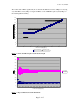
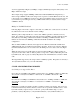
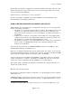
Version 1.0, 4/10/02 KEY WORKLOADS & APPROACHES TO TESTING THE EXAMPLE DESIGN Protocol Performance of IP over ATM vs. Ethernet Figure 1 details the protocol processing required to carry an IP packet over ATM and Ethernet. . Figure 1 – Protocol Processing Figures 2 and 3 show that as the size of the IP packet varies so do the efficiencies of ATM and Ethernet.
Version 1.0, 4/10/02 The result is that ATM is significantly more efficient that Ethernet in terms of Mbps for carrying very small PDUs. Every Mbps of single-cell-PDUs on the ATM link requires (84/55) Mbps on the matching Ethernet link(s).
Version 1.0, 4/10/02 As shown graphically in Figure 3, 622Mbps of single-cell-PDU input requires 622*(84/55) = 949 Mbps of Ethernet output. This example design supplies 800Mbps of Ethernet bandwidth (IXP1240 configurations), so under a single cell/PDU workload the design can be expected to transmit Ethernet at line rate, and to discard the excess ATM input.
Version 1.0, 4/10/02 bytes/minimum frame}. 84 bytes/frame * 8 bits/byte / 100Mb/sec = 6.72 usec/frame. 232MHz * 6.72 usec/frame = 1559 cycles/frame These cycle budgets specify how frequently a cell or frame goes over the wire. If multiple threads handle multiple frames on the same wire, then the budgets are multiplied accordingly.
Version 1.0, 4/10/02 One issue with running simulations unbounded to wire-rate is that it can hide errors because there is no concept of device overflows or underflows. Further the design can become un-balanced, say for example if an efficient receiver races ahead of the rest of the design, hogging shared system resources and potentially penalizing another part of the system. Another approach is to simulate bounded, but to bind to a wire-rate that is faster than the actual wire-rate.
Version 1.0, 4/10/02 Both the OC-12 and 4xOC-3 configurations experience an ATM overflow after 1M cycles. This indicates that under this system workload, the receiver is not keeping up with the wire, but has dropped a cell in the first 6,000 cells. Simulated 40-byte and 1500-byte packet performance2 The OC-12 and 4xOC-3 configurations perform at ATM wire-rate under full-duplex, fullbandwidth 40-byte and 1500-byte packet loads.
Version 1.0, 4/10/02 the number of times the PHY was not fed a cell in time to keep the wire busy, and thus had to manufacture an idle cell. The number reported here is from the 2nd counters query when 2 “_VolgaGetChanCounters” are issued on the same line at the VxWorks prompt (this is because “_VolgaGetChanCounters” prints out the delta between a previous invocation and the present invocation).
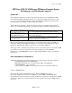
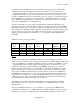
Version 1.0, 4/10/02 degrade in these scenarios, and the design becomes subject to ATM overflows from running “_VolgaGetChanCounters”. Ethernet Input Ports 8 7 6 0 ATM Transmit Rate [%] 84 73 63 0 IXF6012 Transmit Idle N/A N/A N/A N/A ATM Receive Ports 1 1 1 1 IXF6012 Overflows 0 0 0 0 Ethernet Transmit KFrame/s 138 - 147 142 - 148 144 – 148 148,808 Ethernet Transmit [MB/s] 8.8 – 9.4 9.0 – 9.5 9.2 – 9.5 9.
Version 1.0, 4/10/02 Ethernet Input Ports 8 ATM Transmit Rate [%] 100 IXF6012 Transmit Idle 0 ATM Receive Ports 1 IXF6012 Overflows 0 Ethernet Transmit KFrame/s 88,300 Ethernet Transmit [MB/s] 5.6 Figure 8 – Two-cell/PDU Performance on 143MHZ DRAM Using 143 MHz DRAM, the 40-byte (2-cell/PDU) workload performed perfectly, even with 8 Ethernet ports over-subscribing the ATM Transmitter (Figure 8). “_VolgaGetChanCounters” recorded zero ATM Transmit Idle cells and zero ATM Receive overflows.
Version 1.0, 4/10/02 Queue to Core Measurement Technique The performance of the queue-to-core path can be measured by modifying a nominal input data stream such that the entire stream is forwarded to core. For example, changing the IP version in the IP header from 4 to 5 will cause the packets to be forwarded to the core. The lab equipment sends this data stream at a known rate, and the amount of it that gets to the core is measured.
Version 1.0, 4/10/02 RESOURCE UTILIZATION AND HEADROOM ANALYSIS This section details system resource utilization, including per-microengine resources such as registers and microstore instructions; as well as shared resources such as Scratchpad RAM, SRAM, and DRAM. The memory utilization is shown using the default system memory map as shipped.3 One of the ATM utilities, config_print(), prints out the Scratchpad RAM, SRAM, and DRAM address maps to show the memory map in detail.
Version 1.0, 4/10/02 Microstore utilization can be observed by opening a microengine list window with line numbers enabled, and recording the last line number plus 1. Available instructions = 2048 – used instructions. Figure 12 shows the results for each of the three configurations. The CRC Check and CRC Generate microengines apply only to the IXP1200 configuration. In the IXP1200 configuration the ATM Receive and IP Route functions run on the same microengine.
Version 1.0, 4/10/02 SDRAM Capacity The IXM1240 Network Processor Base Card comes with 128MB of SDRAM. The project is configured to use less than 64MB: 32MB of Packet Data Buffers, 16MB for VxWorks, and the balance for IP Route Table Entries. This leaves over 50% available. The IP Route Table Entries live at 0x8100, simply because they do so by default in all the example designs.
Version 1.0, 4/10/02 APPENDIX Buffer Allocation in DRAM The microengines in this example design uses two DRAM command queues. The ordered queue is used by all sdram_crc[] commands to transfer packet data between DRAM and the receive and transmit FIFOs. The priority queue is used for all other microengine DRAM accesses, including access to IP lookup table entries, and modifications to packet headers.