AR-B1890 Intel® Pentium® M / Celeron® M Socket 478 Processor Mini-ITX Board User’s Manual Rev. 1.0 June.
Copyright The trademarks mentioned in the manual are legally registered to their respective companies. Notice The written content provided with this product in the property of Acrosser. No part of this manual may be reproduced, copied, transmitted in any form or by any means without prior written permission of Acrosser. Manual Classification In order to assist in the use of this product, Acrosser has categorized the user manual.
Packing List Please make sure that the following materials before you start installing your board.
Table Of Contents General Information Introduction 5 Specification 6 Block Diagram 8 Mechanical Drawing………………………………………………...
Gigabit LAN / USB Connector ( RJUSB1 ) Ethernet LAN / USB Connector ( RJUSB2 ) Mini - PCI Slot ( MPCI1 ) CompactFlash Slot ( CFD1 ) SoDIMM Slot ( DIMM1 ) SoDIMM Slot ( DIMM 2 ) SATA1 Connector ( SATA1 ) SATA2 Connector ( SATA2 ) PCI - Express Slot ( PCIE1 ) 25 25 25 25 25 25 25 25 25 BIOS Setup AwardBIOS CMOS Setup Utility………………………………….. 26 Standard CMOS Features………………………………………….27 Advanced BIOS Features…………………………………………. 29 Advanced Chipset Features……………………………………….
General Information Introduction The AR-B1890 Mini – ITX board incorporates the Intel® 915GM Express and Intel® I / O controller Hub ICH6 - M chipset , supports the Intel® Pentium® M / Celeron® M processors with 533 / 400 MHz Front Side Bus ( FSB ), Intel® Graphics Media Accelerator 900 ( Intel® GMA 900 ), DDRII 533 MHz system memory, PCI - Express interface, Ethernet / Gigabit LAN, Realtek Audio, LVDS, CompactFlash, Mini – PCI, Serial ATA, USB 2.0.
Specification Board AR-B1890 CPU Up to Intel® Pentium M 2.26G ( 400 / 533MHz FSB ) Celeron® M 1.
I / O Ports Keyboard/ Mouse 1 PS / 2 ports Serial 2 internal RS - 232 ports ( COM 3 / 4 ) 1 external RS – 232 port ( COM 1 ) 1 external RS – 232 / 422 / 485 port ( COM 2 ) VGA 1 VGA port Audio 1 external jack for MIC – In / Line – In / Line – Out LAN 2 external RJ – 45 ports with LED USB 2 internal USB 2.0 ports 4 external USB 2.
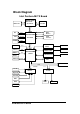
Block Diagram Intel Pentium-M ITX Board Dothan/Yonah Processor IMVP-IV VR CK-410M 478 uFCPGA B S F CRT DDR2 Modules 400/533MHz R/B/G Intel 82915GM LVDS TV-OUT 18 Bit LVDS TVOUT PCI-E 1X PCI-E SATA X 2 SATA Realtek ALC655 I M D Intel 82801FBM IDE X 1 5.1 Channels Marvell 88E8053-A2-NNC LAN1 RealTek RTL8100C/8110S LAN2 PATA 609 BGA CFD X 1 USB2.0 X 6 SDVO Connector PCI-E Gfx / SDVO 1257 FCBGA USB2.
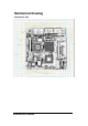
Mechanical Drawing Component side AR-B1890 User’s Manual 9
Solder Side AR-B1890 User’s Manual 10
Hardware Installation Connectors Location Component Side AR-B1890 User’s Manual 11
Solder Side I / O Panel AR-B1890 User’s Manual 12
List of Connectors Connector Function CN1 VGA Display / Audio Connector CN2 Front Audio Connector CN3 COM 3 RS-232 Connector CN4 COM4 RS-232 Connector CN5 CD - In Connector CN6 TV - Out Connector CN7 DVOB Connector CN8 LVDS Connector CN9 ATX Power Connector CN10 IrDA Connector CN11 System Fan Connector CN12 Front Panel Connector CN13 GPIO Connector CN14 CPU Fan Connector PS2-KBMS1 A / B PS2 Keyboard / Mouse Connector FDD1 Slim Floppy Connector IDE1 EIDE Connector COM1 CO
Jumpers Locations List of Jumpers JP3 LVDS Panel Voltage Selection ( +5V / +3.
Jumpers Setting OPEN 1 - 2 - 3 SHORT 1-2 SHORT 2-3 □ ○ ○ ■ ● ○ □ ● ● 1 2 3 1 2 3 1 2 3 LVDS Panel Voltage Selection ( JP3 ) 5V 1 □ 3.
COM2 RS232/422/485 Selection ( JP6,JP7 ) COM2 SETTING RS232 JP6 JP7 1 ■ ● 2 3 ○ 1 ■ ● 2 4 ● ● 5 6 ○ 3 ○ ○ 4 7 ● ● 8 9 ○ 5 ○ ○ 6 10 ● ● 11 12 ○ COM2 SETTING RS422 JP6 JP7 1 □ 2 ● ● 3 1 □ ○ 2 4 ○ 5 ● ● 6 3 ● ● 4 7 ○ 8 ● ● 9 5 ○ ○ 6 10 ○ 11 ● ● 12 COM2 SETTING RS485 JP6 JP7 1 □ 2 ● ● 3 1 □ ○ 2 4 ○ 5 ● ● 6 3 ○ ○ 4 7 ○ 8 ● ● 9 5 ● ● 6 10 ○ 11 ● ● 12 AR-B1890 User’s Manual 16
VGA Display Connector ( CN1 ) Pin Assignment Pin Assignment 1 RED 2 GREEN 3 BLUE 4 N/C 5 GND 6 GND 7 GND 8 GND 9 VGA_VCC 10 GND 11 N/C 12 CRT _ DDCDATA 13 HSYNC 14 VSYNC 15 CRT_DDCCLK 5.
COM4 RS-232 Connector ( CN4 ) Pin Assignment Pin Assignment 1 DCD4# 2 RXD4 3 TXD4 4 DTR4# 5 GND 6 DSR4# 7 RTS4 8 CTS4# 9 RI4# 10 N/C CD - In Connector ( CN5 ) Pin Assignment 1 CD-L 2 GND 3 GND 4 CD-R TV - Out Connector ( CN6 ) Pin Assignment Pin Assignment 1 Y 2 C 3 GND 4 GND 5 CVBS 6 N/C 7 GND 8 N/C AR-B1890 User’s Manual 18
DVOB Connector ( CN7 ) Pin Assignment Pin Assignment 1 5V 2 3.3V 3 SDVOB_INT# 4 SDVOB_INT 5 2.
LVDS Connector ( CN8 ) Pin Assignment Pin Assignment 1 BKL _ EN 2 BKL _ CTL 3 LVDS _ VCC 4 GND 5 LVDS _ CH1 _ CLK- 6 LVDS _ CH1 _ CLK+ 7 LVDS _ VCC 8 GND 9 LVDS _ CH1 _ DATA0- 10 LVDS _ CH1 _ DATA0+ 11 LVDS _ CH1 _ DATA1- 12 LVDS _ CH1 _ DATA1+ 13 LVDS _ CH1 _ DATA2- 14 LVDS _ CH1 _ DATA2+ 15 N/C 16 N/C 17 N/C 18 N/C 19 LVDS _ CH2 _ DATA0- 20 LVDS _ CH2 _ DATA0+ 21 LVDS _ CH2 _ DATA1- 22 LVDS _ CH2 _ DATA1+ 23 LVDS _ CH2 _ DATA2- 24 LVDS _ CH2 _ DATA2+ 25
IrDA Connector ( CN10 ) Pin Assignment 1 5V 2 CIRTX 3 IRRX 4 GND 5 IRTX 6 CIRRX System Fan Connector ( CN11 ) Pin Assignment 1 GND 2 12V 3 FAN Sense Front Panel Connector ( CN12 ) Pin Assignment Pin Assignment 1 GND 2 Power Switch 3 BUZZER- 4 BUZZER+ 5 HD_LED- 6 HD_LED+ 7 POWER LED- 8 Power LED+ 9 GND 10 Reset AR-B1890 User’s Manual 21
GPIO Connector ( CN13 ) Pin Assignment 1 GPI 2 GPO 3 GPI 4 GPO 5 GPI 6 GPO 7 GPI 8 GPO 9 5V 10 GND CPU Fan Connector ( CN14 ) Pin Assignment 1 GND 2 12V 3 FAN Sense PS2 KB / MS Connector ( PS2-KBMS1 A / B ) Pin Assignment Pin Assignment 1 KB_DATA 2 N/C 3 GND 4 KB_VCC 5 KB_CLK 6 N/C 7 MS_DATA 8 N/C 9 GND 10 KB_VCC 11 MS_CLK 12 N/C AR-B1890 User’s Manual 22
EIDE Connector ( IDE1 ) Pin Assignment Pin Assignment 1 IDERST# 2 GND 3 PID7 4 PID8 5 PID6 6 PID9 7 PID5 8 PID10 9 PID4 10 PID11 11 PID3 12 PID12 13 PID2 14 PID13 15 PID1 16 PID14 17 PID0 18 PID15 19 GND 20 N/C 21 PDREQ 22 GND 23 PIOR# 24 GND 25 PIOR# 26 GND 27 PRDY 28 GND 29 PACK# 30 GND 31 PIRQ14 32 N/C 33 PPDA1 34 ATA66 _ DET 35 PPDA0 36 PPDA2 37 PPCS1# 38 PPCS3# 39 HDLED# 40 GND USB Connector ( USB1 ) Pin Assignment Pi
Slim Floppy Connector ( FDD1 ) Pin Assignment Pin Assignment 1 VCC 2 INDEX# 3 VCC 4 DRV _ SEL# 5 VCC 6 DSK _ CH# 7 N/C 8 N/C 9 N/C 10 MOTOR# 11 N/C 12 DIR# 13 DENSEL# 14 STEP# 15 GND 16 WDATA# 17 GND 18 WGATE# 19 GND 20 TRACK# 21 GND 22 WPROT# 23 GND 24 RDATA# 25 GND 26 SIDE# COM1 RS-232 Connector ( COM1 ) Pin Assignment Pin Assignment 1 DCD1# 2 RXD1 3 TXD1 4 DTR1# 5 GND 6 DSR1# 7 RTS1# 8 CTS1# 9 RI1# COM2 RS-232/422/485 Connector
Gigabit LAN / USB Connector ( RJUSB1 ) Standard RJ - 45 Connector / Standard USB Connector Ethernet LAN / USB Connector ( RJUSB2 ) Standard RJ - 45 Connector / Standard USB Connector Mini - PCI Slot ( MPCI1 ) Standard Mini - PCI Connector CompactFlash Slot ( CFD1 ) Standard CompactFlash Connector Type II SoDIMM Slot ( DIMM1 ) Standard DDRII SoDIMM Connector SoDIMM Slot ( DIMM 2 ) Standard DDRII SoDIMM Connector SATA1 Connector ( SATA1 ) Standard Serial ATA Connector SATA2 Connector ( SATA2 ) Standard
BIOS Setup BIOS (Basic Input and Out System) includes a CMOS Setup utility which allows user to configure required settings or to activate certain system features. When the power is turned on, pushing the button during the Power-On Self test will take you to the CMOS Setup screen. If you still wish to enter Setup, restart the system by pressing the , and keys. You can also restart by turning the system Off and back On again.
Standard CMOS Features Phoenix – AwardBIOS CMOS Setup Utility Standard CMOS Features Date (mm:dd:yy) Time (hh:mm:ss) Thu, Dec 15 2005 10 : 59 : 36 IDE Channel 0 Master IDE Channel 0 Slave IDE Channel 1 Master IDE Channel 0 Slave [ None ] [ None ] [ None ] [ None ] Drive A Drive B [ 1.44M, 3.
Cylinder Head Precomp Landing Zone Sector Number of cylinders Number of heads Write precomp Landing zone Number of sectors Access Mode CHS LBA Large Auto HD < 528MB HD > 528MB For MS-DOS only Drive A / Drive B 360KB, 5.25” 5.25” inch 360KB PC-type standard drive. 1.2MB, 5.25” 720KB, 3.5” 1.44MB, 3.5” 2.88MB, 3.5” 5.25” inch 1.2MB AT-type high-density drive. 3.5” inch 720KB double-sided drive. 3.5” inch 1.44MB double-sided drive. 3.5” inch 2.88MB double-sided drive.
Advanced BIOS Features Phoenix – AwardBIOS CMOS Setup Utility Advanced BIOS Features CPU Features Hard Disk Boot Priority Virus Warning CPU L1 & L2 Cache Quick Power On Self Test First Boot Device Second Boot Device Third Boot Device Boot Other Device Swap Floppy Driver Boot Up Floppy Seek Boot Up NumLock Status Gate A20 Option Typematic Rate Setting Typematic Rate (Chars/Sec) Typematic Delay Security Option APIC Mode MPS Version Control For OS Os Select For DRAM >64MB Report No FDD For Win 95 Small Logo(EP
CPU L1&L2 Cache This option allows you to enable or disable the cache function. Quick Power On Self Test When this option enabled, this field speeds up the Power On Self Test after the system is turned on. First/Second/Third Boot Device Floppy Select your boot device priority by Floppy. LS120 Select your boot device priority by LS120. Hard Disk Select your boot device priority by Hard Disk. CDROM Select your boot device priority by CDROM. ZIP Select your boot device priority by ZIP.
Typematic Rate (Chars/Sec) When enabled, the system registers repeated keystrokes speeds. Setting are from 6 to 30 characters per second. Typematic Delay When enabled, this option allows you to set the time interval for displaying the first and second characters. Security Option When setup, the system always boots up and prompt for the Supervisor Password only. When system, the system prompts for the User Password every time you boot up.
Advanced Chipset Features Phoenix – AwardBIOS CMOS Setup Utility Advanced Chipset Features DRAM Timing Selectable CAS Latency Time DRAM RAS# to CAS# Delay DRAM RAS# Precharge Precharge delay (tRAS) System Memory Frequency SLP_S4# Assertion Width System BIOS cacheable Video BIOS cacheable Memory Hole At 15M-16M PCI Express Root Port Func [ By SPD ] 4 4 4 11 533MHz [ 4 to 5 Sec.
DRAM RAS# to CAS# Delay This option allows you to insert a delay between RAS and CAS signals. DRAM RAS# Precharge Precharge delay ( tRAS ) This option sets the number of cycles required for the RAS to accumulate its charge before the DRAM refreshes. The default setting Precharge delay is 8. SLP_S4# Assertion Width The default is 4 to 5 Sec. System BIOS cacheable When enabled, the system BIOS ROM at F0000h-FFFFFh. Video BIOS cacheable When enabled, the video BIOS ROM at C0000h-F7FFFh.
Integrated Peripherals Phoenix – AwardBIOS CMOS Setup Utility Integrated Peripherals OnChip IDE Device Onboard Device Super IO Device Watch Dog Timer Select Onboard Serial Port 5 Serial Port 5 Use IRQ Onboard Serial Port 6 Serial Port 5 Use IRQ [ Press Enter ] [ Press Enter ] [ Press Enter ] [ Disabled ] [ 4F8 ] [ IRQ5 ] [ 4E8 ] [ IRQ7 ] Item Help Menu Level > ↑↓→←:Move Enter:Select +/-/PU/PD:Value F10:Save ESC:Exit F1:General Help F5:Previous Values F6:Fail-Safe Defaults F7:Optimized Defaults Phoenix
IDE Primary / Secondary Master / Slave PIO The PIO allows the BIOS to communicate with the controller and CPU directly. When Auto is selected, the BIOS will select the best available mode. IDE Primary / Secondary Master / Slave UDMA These option allow your disk I/O 33Mb/sec to Ultra DMA 33 feature. On-Chip Serial ATA The default is Auto. Phoenix – AwardBIOS CMOS Setup Utility Onboard Device USB Controller USB 2.
Phoenix – AwardBIOS CMOS Setup Utility Super IO Device Onboard FDC Controller Onboard Serial Port 1 Onboard Serial Port 2 [ Enabled ] [ 3F8/IRQ4 ] [ 2F8/IRQ3 ] Item Help Menu Level > ↑↓→←:Move Enter:Select +/-/PU/PD:Value F10:Save ESC:Exit F1:General Help F5:Previous Values F6:Fail-Safe Defaults F7:Optimized Defaults Onboard FDC Controller This option allows you to select FDD port. Onboard Serial Port 1 The default values is 3F8/IRQ4. Onboard Serial Port 2 The default values is 2F8/IRQ3.
Power Management Setup Phoenix – AwardBIOS CMOS Setup Utility Power Management Setup ACPI Function ACPI Suspend Type Run VGABIOS if S3 Resume Power Management Video Off Method Video Off In Suspend Suspend Type MODEM Use IRQ Suspend Mode HDD Power Down Soft-Off by PWR-BTTN Wake-Up by PCI card Power On by Ring USB KB Wake-up From S3 Resume by Alarm Date(of Month) Alarm Time(hh:mm:ss) Alarm [ Enabled ] [ S1(POS) ] Auto [ User Define ] [ DPMS ] [ Yes ] [ Stop Grant ] [3] [ Disabled ] [ Disabled ] [ Instant-Off
Video Off Method V/H SYNC+Blank DPMS Blank Screen Blank the screen and turn off vertical and horizontal scanning. Allows BIOS to control the video display. Writes blanks to the video buffer. Video Off In Suspend Select the Video Off in Suspend mode. Suspend Type The default is Stop Grant. MODEM Use IRQ This option allows you to set the IRQ by Modem. Suspend Mode After the set time of system inactivity, all devices except CPU will be shut off.
PnP / PCI Configurations Phoenix – AwardBIOS CMOS Setup Utility PnP/PCI Configurations Init Display First Reset Configuration Data [ PCI Slot ] [ Disabled ] Resources Controlled By IRQ Resources DMA Resources [ Auto(ESCD) ] Press Enter Press Enter PCI/VGA Palette Snoop [ Disabled ] ** PCI Express relative items ** Maximum Payload Size [ 4096 ] Item Help Menu Level > Default is Disabled.
PC Health Stutas Phoenix – AwardBIOS CMOS Setup Utility PC Health Status Shutdown Temperature VCPU VMemory V3.3V V5V V+12V V-12V V5VSB Voltage Battery Temperature CPU Temperature GMCH Temperature System Fan CPU Speed Fan System Speed [ 60°C~140°F ] 1.26V 1.76V 3.26V 4.97V 11.77V (-)11.78V 4.97V 3.
Load Fail – Safe Defaults This menu contains the most appropriate values of the system parameters that allow minimum system performance. Load Optimized Defaults This menu allows you to load the factory defaults for BIOS and Chipset features which the system automatically detects. Set Supervisor Password When you select this function, the following message will appear at the center of the screen to assist you creating a password. Type the password, up to eight characters and press .
Drivers Installation Install Chipset Drivers 1. Insert the AR-B1890 CD-ROM into your CD-ROM drive. Click Intel® 915GMchipsets Drivers. 2. Click Intel® Chipset software Installation Utility. 3. When the welcome screen appears, click Next to continue. 4. Click Yes to accept the software license agreement and proceed with the installation process. 5. On readme information screen, click Next to continue the installation. 6. The setup process is complete now.
Install Marvell GigaLAN Drivers 1. Insert the AR-B1890 CD-ROM into your CD-ROM drive. Click LAN Card and Marvell LAN controller Driver. 2. When the welcome screen appears, click Next to continue 3. Click Yes to accept the software license agreement and continue the installation. 4. On readme information screen, click Next to continue the installation. 5. The setup process is complete now. Click Finish to restart the computer and for changes to take effect. Install Realtek Ethernet Drivers 1.