PCA-6175 Pentium® II processorbased PCI/ISA-bus CPU card
Copyright Notice This document is copyrighted, 1998, by Advantech Co., Ltd. All rights are reserved. Advantech Co., Ltd., reserves the right to make improvements to the products described in this manual at any time without notice. No part of this manual may be reproduced, copied, translated or transmitted in any form or by any means without the prior written permission of Advantech Co., Ltd. Information provided in this manual is intended to be accurate and reliable. However, Advantech Co., Ltd.
A Message to the Customer Advantech Customer Services Each and every Advantech product is built to the most exacting specifications to ensure reliable performance in the harsh and demanding conditions typical of industrial environments. Whether your new Advantech equipment is destined for the laboratory or the factory floor, you can be assured that your product will provide the reliability and ease of operation for which the name Advantech has come to be known. Your satisfaction is our primary concern.
Product Warranty Advantech warrants to you, the original purchaser, that each of its products will be free from defects in materials and workmanship for one year from the date of purchase. This warranty does not apply to any products which have been repaired or altered by persons other than repair personnel authorized by Advantech, or which have been subject to misuse, abuse, accident or improper installation. Advantech assumes no liability under the terms of this warranty as a consequence of such events.
Initial inspection Before you begin installing your card, please make sure that the following materials have been shipped: • 1 PCA-6175 Pentium® II single board computer • 1 Pentium II CPU and cooling fan (optional) • 1 PCA-6175 user's manual • 1 bus master & BIOS utility driver • 1 FDD cable • 2 EIDE HDD cables • 1 printer cable • 1 ivory cable for keyboard and mouse • 1 ATX-to-PS/2 power cable • 1 Pentium II CPU retention module If any of these items are missing or damaged, contact your distributor or sal
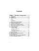
Contents Chapter 1 Hardware Configuration ....... 1 1.1 Introduction ............................................................ 2 1.2 Features .................................................................. 3 1.3 Specifications ........................................................ 4 System .................................................................................................. 4 Memory .................................................................................................
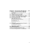
Chapter 2 Connecting Peripherals ..... 23 2.1 Primary (CN6) and Secondary (CN7) IDE Connectors ........................................................... 24 2.2 Floppy Drive Connector (CN13) .......................... 24 2.3 Parallel Port Connector (CN8) ............................ 25 2.4 Keyboard & PS/2 Mouse Connector (CN12) ...... 25 2.5 Serial Ports (CN9: COM1; CN10: COM2) ............ 26 2.6 Front Panel Connectors (CN2, CN3, CN4, J1 and J2)................................. 27 2.6.
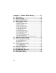
Chapter 3 Award BIOS Setup .............. 31 3.1 3.2 3.3 3.4 Introduction .......................................................... 32 Entering Setup ..................................................... 32 Standard CMOS Setup......................................... 32 BIOS Features Setup ........................................... 33 3.4.1 Virus Warning ............................................................................ 33 3.4.2 Quick Power On Self Test .........................................
Appendix A Programming the Watchdog Timer ................................ 43 Programming the Watchdog Timer ............................ 44 Appendix B Pin Assignments ............. 47 B.1 COM1/COM2 RS-232 Serial Port (CN9,CN10) .... 48 B.2 Keyboard and Mouse Connnector (CN12) ......... 48 B.3 External Keyboard Connector (J10) ................... 48 B.4 ATX Feature Connector (J7) ............................... 49 B.5 IDE Hard Drive Connector (CN6, CN7) ............... 49 B.6 USB Connector (CN11) .........
x
CHAPTER 1 Hardware Configuration This chapter gives background information on the PCA-6175. It then shows you how to configure the card to match your application and prepare it for installation into your PC.
1.1 Introduction The PCA-6175 industrial grade CPU card uses Intel's highly acclaimed Pentium® II processor and Intel 440LX PCI chipset. The card works with standard ISA or PCI/ISA-bus passive backplanes. The CPU provides 512 KB on-chip L2 cache, eliminating the need for external SRAM chips. It has two PCI EIDE interfaces (for up to four devices), and an FDD interface (for up to two devices).
1.2 Features • Intel slot 1architecture • Pentium® II processor up to 333 MHz • Intel 82440LX PCIset • Three DIMM sockets for SDRAM up to 384 MB; supports ECC • Award Flash BIOS • On-board ATX power control connector to meet ACPI requirements • Two enhanced IDE ports, supporting Ultra DMA/33, PIO Mode 4 and DMA Mode 2 • Two USB ports • Two serial ports • One bidirectional parallel port, supports ECP/EPP/SPP • One floppy port and one keyboard/mouse port • PCI V2.1 compliant • PICMG 2.
1.3 Specifications System • CPU: Intel Pentium® II up to 333 MHz • BIOS: Award Flash BIOS • Green function: Supports power management operation via BIOS. Activated by keyboard or mouse activity • PCI enhanced IDE hard disk drive interface: Supports up to four IDE (AT bus) large hard disk drives (up to 8.4 GB), or other enhanced IDE devices. Supports PIO Mode 4 (16.67 MB/s data transfer rate) and Ultra DMA/33 (33 MB/s data transfer rate).
• Enhanced parallel port: Configurable to LPT1, LPT2, LPT3 or disabled. Standard DB-25 female connector provided. Supports EPP/ECP/SPP • Serial ports: Two RS-232 ports with 16C550 UARTs (or compatible) with 16-byte FIFO buffer. Supports speeds up to 115.2 Kbps. Ports can be individually configured to COM1, COM2 or disabled • Keyboard and PS/2 mouse connector: A 6-pin mini DIN connector is located on the mounting bracket for easy connection to a keyboard or PS/2 mouse.
Metal bracket for stability 6 PCA-6175 User's Manual Intel Pentium® II processor up to 333 MHz Intel 82440LX PCIset Accommodates three DIMM modules, up to 384 MB EIDE connectors DiskOnChip® 2000 Flash disk Bi-directional parallel port ATX feature connector Keyboard/ Mouse connector COM2 COM1 USB ports FDD connector 1.
1.5 Jumpers and Connectors Connectors on the PCA-6175 board link it to external devices such as hard disk drives and a keyboard. In addition, the board has a number of jumpers used to configure your system for your application. The tables below list the function of each of the board jumpers and connectors. Later sections in this chapter give instructions on setting jumpers. Chapter 2 gives instructions for connecting external devices to your card.
Table 1-2: Connectors Number Function CN1 Infrared (IR) connector CN2 Keyboard lock CN3 External speaker CN4 IDE LED CN5 CPU fan connector CN6 Primary IDE connector CN7 Secondary IDE connector CN8 Parallel port CN9 Serial port: COM 1 CN10 Serial port: COM 2 CN11 USB port CN12 PS/2 keyboard and mouse CN13 Floppy drive connector CN14 (Reserved) J1 ATX soft power switch J2 Reset J3 External SMI J7 ATX feature connector J10 External keyboard connector RT1 (Reserved) 8 PCA-6175 User's Manual
1.
1.
1.8 Safety Precautions Warning! Always completely disconnect the power cord from your chassis whenever you work with the hardware. Do not make connections while the power is on. Sensitive electronic components can be damaged by sudden power surges. Only experienced electronics personnel should open the PC chassis. Caution! Always ground yourself to remove any static charge before touching the CPU card. Modern electronic devices are very sensitive to static electric charges.
1.9 Jumper Settings This section provides instructions on how to configure your card by setting jumpers. It also includes the card's default settings and your options for each jumper. 1.9.1 How to set jumpers You configure your card to match the needs of your application by setting jumpers. A jumper is the simplest kind of electric switch. It consists of two metal pins and a small metal clip (often protected by a plastic cover) that slides over the pins to connect them.
1.9.3 CMOS clear (J6) The PCA-6175 CPU card contains a jumper that can erase CMOS data and reset the system BIOS information. Normally this jumper should be set with pins 1-2 closed. If you want to reset the CMOS data, set J6 to 2-3 closed for just a few seconds, and then move the jumper back to 1-2 closed. This procedure will reset the CMOS to its default setting. Table 1-4: CMOS clear jumper settings (J6) Function Jumper setting Keep CMOS data 1-2 closed Clear CMOS data 2-3 closed 1 1 1.9.
1.9.5 CPU bus clock select (J11) The CPU clock varies according to the Pentium® II processor's CPU bus clock. There are two settings for the CPU clock, 66.6 MHz and 75 MHz. Table 1-6: CPU clock select jumper settings (J11) Function Jumper setting 66.6 MHz 1-2 closed 75 MHz 2-3 closed 1 1 Note: 14 75 MHz exceeds the product's specifications.
1.9.6 DiskOnChip® 2000 Flash disk address select (J12) The PCA-6175 includes a 32-pin socket for M-System's DiskOnChip 2000 Flash disk module. This revolutionary solid state disk enables critical system information to be stored within an on-board Flash disk for virtually instantaneous data access. You must specify the memory address you wish to use for your DiskOnChip 2000 Flash disk module by setting jumper (J12).
1.10 System Memory The top-left edge of the PCA-6175 contains three sockets for 168-pin dual inline memory modules (DIMMs). All three sockets use 3.3 V unbuffered synchronous DRAMs (SDRAM). DIMMs are available in capacities of 16, 32, 64 or 128 MB. The sockets can be filled in any combination with DIMMs of any size, giving your PCA-6175 single board computer between 16 and 384 MB of memory.
1.10.2 Supplementary information about DIMMs Your PCA-6175 can accept four kinds of memory chips: EDO (with or without parity), and SDRAM (with or without parity). Also: • SDRAM chips are usually thinner and have higher pin density than EDO chips. • The BIOS displays EDO and SDRAM memory on the boot-up screen. • Chips with 9 chips/side support parity; chips with 8 chips/side do not support parity. • Single-sided modules are typically 16 or 64 MB; double-sided modules are usually 8, 32 or 128 MB.
1.11 Memory Installation Procedures To install DIMMs, first make sure the two handles of the DIMM socket are in the "open" position. i.e. The handles remain outward. Slowly slide the DIMM module along the plastic guides on both ends of the socket. Then press the DIMM module right down into the socket, until you hear a click. This is when the two handles have automatically locked the memory module into the correct position of the DIMM socket. (See Figure 1-3.
1.12 Cache Memory Since the second level cache has been embedded into the Pentium® II CPU, you do not have to take care of either SRAM chips or SRAM modules. The built-in second level cache in the Pentium II yields much higher performance than the external cache memories. The cache size in the Pentium II CPU is either 256 KB or 512 KB. Normally, for workstation and server application, the 256 KB version is enough. However, if your system is for heavy duty applications, the 512 KB version will help a lot.
1.13 Mounting the CPU and Cooling Modules The Pentium® II is a module-type CPU which runs at high speeds, for exampe 233 ~ 333 MHz, so the cooling mechanism becomes critical for system reliability. There are two types of cooling methods: one with a cooling fan attached to the heat sink of the Pentium II module, the other with a huge heat sink without any cooling fan attached. Both cooling methods for the Pentium II require a "retention module" to firmly fix the Pentium II CPU to slot 1.
Figure 1-5: Mounting CPU and cooling modules - Step 2 Step 2 Step 3 Figure 1-6: Mounting CPU and cooling modules - Step 3 Chapter 1 Hardware Configuration 21
1.14 On-board Support Bracket Advantech's PCA-6175 Pentium® II also includes an on-board metal bracket to provide balanced support for the Pentium II processor cartridge.
CHAPTER 2 Connecting Peripherals This chapter tells how to connect peripherals, switches and indicators to the PCA-6175 board. You can access most of the connectors from the top of the board while it is installed in the chassis. If you have a number of cards installed, or your chassis is very tight, you may need to partially remove the card to make all the connections.
2.1 Primary (CN6) and Secondary (CN7) IDE Connectors You can attach up to four IDE (Integrated Device Electronics) drives to the PCA-6175’s internal controller. The primary (CN6) and secondary (CN7) connectors can each accommodate two drives. Wire number 1 on the cable is red or blue and the other wires are gray. Connect one end to connector CN6 or CN7 on the CPU card. Make sure that the red/blue wire corresponds to pin 1 on the connector (in the upper right hand corner).
2.3 Parallel Port Connector (CN8) The parallel port is normally used to connect the CPU card to a printer. The PCA-6175 includes an on-board parallel port, accessed through a 26-pin flat-cable connector, CN8. The card comes with an adapter cable which lets you use a traditional DB-25 connector. The cable has a 26-pin connector on one end and a DB-25 connector on the other, mounted on a retaining bracket. The bracket installs at the end of an empty slot in your chassis, giving you access to the connector.
2.5 Serial Ports (CN9: COM1; CN10: COM2) The PCA-6175 offers two serial ports, CN1 as COM1 and CN2 as COM2. These ports can connect to serial devices (such as a mouse, printers, and so on) or to a communication network. Table 2-1: Serial port connections (COM1, COM2) Connector CN9 CN10 Ports COM1 COM2 Address 3F8*, 3E8 2F8*, 2E8 Interrupt IRQ4 IRQ3 * default settings The IRQ and address ranges for both ports are fixed.
2.6 Front Panel Connectors (CN2, CN3, CN4, J1 and J2) There are several external switches to monitor and control the PCA-6175. 2.6.1 Keyboard lock and power on LED (CN2) CN2 is a 5-pin connector for the keyboard lock and power on LED connection. Refer to Appendix B.12 for detailed information on the pin assignments. If a PS/2 power supply is used, the system's power LED status will be one of the following: PS/2 Power Mode LED Status System On On System Suspend Flashes eight times/sec.
2.7 ATX Power Control Connectors (J7 and J1) 2.7.1 ATX feature connector (J7) and soft power switch connector (J1) The PCA-6175 can support an advanced soft power switch function if an ATX power supply is used. To enable the soft power switch function: 1. Take the specially designed ATX-to-PS/2 power cable out of the PCA-6175's accessory bag. 2. Connect the 3-pin plug of the cable to J7 (ATX feature connector). 3. Connect the power on/off button to J1. (A momentary type of button should be used.
2.7.2 Controlling the soft power switch It is easy to control the ATX soft power switch. Pushing the button once will switch the system between the "On" and "Suspend" power modes. Pushing the button for more than 4 seconds while in the "On" mode will turn the system off. Users can also identify the current power mode through the system's power LED, as indicated below: ATX Power Mode LED Status 2.8 System On On System Suspend Flashes eight times/sec. System Off Flashes once/sec.
2.11 External Suspend Switch Lead (SMI) (J3) This allows the user to manually place the system into a suspend mode or "Green" mode when the system is not in use. System activity is decreased to save electricity and prolong the life of certain components. The 2-pin connector connects to the case-mounted suspend switch. If you do not have a switch for the connector, you may use the "turbo switch", because it does not have any other function. SMI is activated when it detects a "short to open" moment.
CHAPTER 3 Award BIOS Setup This chapter describes how to set the card’s BIOS configuration data.
3.1 Introduction Award’s BIOS ROM has a built-in setup program that allows users to modify the basic system configuration. This type of information is stored in battery-backed RAM so that it retains the setup information when the power is turned off. 3.2 Entering Setup Turn on the computer and press immediately, to allow you to enter the setup. 3.3 Standard CMOS Setup Choose the “STANDARD CMOS SETUP” option from the "INITIAL SETUP SCREEN" menu, and the screen below will be displayed.
3.4 BIOS Features Setup The “BIOS FEATURES SETUP” screen appears when choosing the "BIOS FEATURES SETUP" item from the "CMOS SETUP UTILITY" menu. It allows the user to configure the PCA-6175 according to his particular requirements. Below are some major items that are provided in the BIOS FEATURES SETUP screen: Figure 3-2: BIOS features setup screen 3.4.
3.4.2 Quick Power On Self Test This option speeds up the Power-On Self Test (POST) conducted as soon as the computer is turned on. When enabled, BIOS shortens or skips some of the items during the test. When disabled, the computer conducts normal POST procedures. 3.4.3 Boot Sequence This function determines the sequence in which the computer will search the drives for the disk operating system (i.e. DOS). The BIOS provides the folllowing boot sequences: A,C, SCSI C,A.
3.4.5 Boot Up NumLock Status The default is “On”. On Keypad boots up to number keys. Off Keypad boots up to arrow keys. 3.4.6 Boot Up System Speed High Sets the speed to high. Low Sets the speed to low. 3.4.7 IDE HDD Block Mode Enabled Enable IDE HDD Block Mode. BIOS will detect the block size of the HDD and send a block command automatically. Disabled Disable IDE HDD Block Mode. 3.4.8 Gate A20 Option Normal The A20 signal is controlled by the keyboard controller or chipset hardware.
3.4.11 Typematic Delay (msec) Typematic delay is the time interval between the appearance of the first and second characters, when holding down a key. The input values for this category are: 250, 500, 750, 1000 (msec). 3.4.12 Security Option This setting determines whether the system will boot up if the password is denied. Access to Setup is, however, always limited. System The system will not boot, and access to Setup will be denied if the correct password is not entered at the prompt.
3.5 CHIPSET Features Setup By choosing the “CHIPSET FEATURES SETUP” option from the INITIAL SETUP SCREEN menu, the screen below will be displayed. This sample screen contains the manufacturer’s default values for the PCA-6175. Figure 3-3: CHIPSET features setup screen Note: If you enable the IDE HDD block mode, the enhanced IDE driver will be enabled.
3.6 Power Management Setup The power management setup controls the CPU card's “green” features. The following screen shows the manufacturer’s defaults. Figure 3-4: Power management setup screen 3.6.1 Power Management This option allows you to determine if the values in power management are disabled, user-defined, or predefined. 3.6.2 HDD Power Management You can choose to turn the HDD off after one of the time intervals listed, or when the system is in Suspend mode.
3.6.3 IRQ Activity IRQ can be set independently. Activity on any enabled IRQ will wake up the system. 3.7 PCI Configuration Setup Figure 3-5: PCI configuration screen 3.7.1 Load BIOS Defaults “LOAD BIOS DEFAULTS” indicates the most appropriate values for the system parameters for minimum performance. These default values are loaded automatically if the stored record created by the setup program becomes corrupted (and therefore unusable). 3.7.
3.
3.9 Password Setting To change the password: 1. Choose the "PASSWORD SETTING" option from the Setup main menu and press . The screen will display the following message: Enter Password: Press . 2. If the CMOS is good or if this option has been used to change the default password, the user is asked for the password stored in the CMOS. The screen will display the following message: Confirm Password: Enter the current password and press . 3.
3.11 Save & Exit Setup If you select this and press , the values entered in the setup utilities will be recorded in the CMOS memory of the chipset. The microprocessor will check this every time you turn your system on and compare this to what it finds as it checks the system. This record is required for the system to operate. 3.12 Exit Without Saving Selecting this option and pressing lets you exit the setup program without recording any new values or changing old ones.
APPENDIX A Programming the Watchdog Timer The PCA-6175 is equipped with a watchdog timer that resets the CPU or generates an interrupt if processing comes to a standstill for any reason. This feature ensures system reliability in industrial standalone or unmanned environments.
Programming the Watchdog Timer To program the watchdog timer, you must write a program which writes I/O port address 443 (hex). The output data is a time interval value. The value range is from 01 (hex) to 3F (hex), and the related time interval is 1 sec. to 63 sec. 44 Data Time Interval 01 1 sec. 02 2 sec. 03 3 sec. 04 4 sec. • • • • • • 3F 63 sec.
After data entry, your program must refresh the watchdog timer by rewriting I/O port 443 (hex) while simultaneously setting it. When you want to disable the watchdog timer, your program should read I/O port 443 (hex).
46 PCA-6175 User's Manual
APPENDIX B Pin Assignments This appendix contains information of a detailed or specialized nature.
B.1 COM1/COM2 RS-232 Serial Port (CN9,CN10) Table B-1: COM1/COM2 RS-232 serial port (CN9) Pin 1 2 3 4 5 6 7 8 9 B.2 Signal DCD RXD TXD DTR GND DSR RTS CTS RI Keyboard and Mouse Connnector (CN12) Table B-2: Keyboard and mouse connector (CN12) B.
B.4 ATX Feature Connector (J7) Table B-4: ATX feature connector (J7) B.5 Pin Signal 1 2 3 5VSB NC PS-ON IDE Hard Drive Connector (CN6, CN7) 39 37 .... 3 1 40 38 ....
B.6 USB Connector (CN11) 1 2 9 10 Table B-6: USB1/USB2 connector (CN11) Pin 1 3 5 7 9 B.
B.8 Floppy Drive Connector (CN13) 33 31 .... 3 1 34 32 ....
B.9 Parallel Port Connector (CN8) 13 12 .... 2 1 26 25 ....
B.10 IR Connector (CN1) Table B-10: IR connector (CN1) Pin 1 2 3 4 5 Signal +5 V N/C IR_RX GND IR_TX B.11 HDD LED Connector (CN4) Table B-11: HDD LED connector Pin 1 2 Signal V CC LED B.12 Power LED and Keylock Connector (CN2) You can use an LED to indicate when the CPU card is on. Pin 1 of CN2 supplies the LED's power, and Pin 3 is the ground. You can use a switch (or a lock) to disable the keyboard so that the PC will not respond to any input.
B.13 External Speaker (CN3) The CPU card has its own buzzer. You can also connect it to the external speaker on your computer chassis.
B.14 System I/O Ports Table B-14: System I/O ports Addr.
B.15 DMA Channel Assignments Table B-15: DMA channel assignments Channel 0 1 2 3 4 5 6 7 Function Available Available Floppy disk (8-bit transfer) Available Cascade for DMA controller 1 Available Available Available B.
B.17 1st MB Memory Map Table B-17:1st MB memory map Addr.
58 PCA-6175 User's Manual
APPENDIX C DOC® 2000 Installation Guide This appendix contains information on the DiskOnChip® 2000 quick installation guide.
C.1 DiskOnChip® 2000 Quick Installation Guide C.1.1 DiskOnChip 2000 installation instructions 1. Make sure the target platform is powered OFF. 2. Plug the DiskOnChip® 2000 device into its socket. Verify the direction is correct (pin 1 of the DiskOnChip® 2000 is aligned with pin 1 of the socket). 3. Power up the system. 4. During power up you may observe the messages displayed by the DiskOnChip® 2000 when its drivers are automatically loaded into the system's memory. 5.
C.1.2 Additional information and assistance 1. Visit M-Systems' Web site at www.m-sys.com where you can find Utilities Manual, Data Sheet and Application Notes. In addition, you can find the latest DiskOnChip® 2000 S/W Utilities. 2. Contact your dealer for technical support if you need additional assistance, and have the following information ready: • Product name and serial number. • Description of your computer hardware (manufacturer, model, attached devices, etc.
62 PCA-6175 User's Manual